Installation Instructions PowerFlex 700 Adjustable Frequency AC Drive – Frames 0…6 0.37…132 kW (0.5…200 Hp) This document explains the 5 BASIC STEPS needed to install and perform a Basic Start-Up of the PowerFlex 700 (Series A or B) AC drive. A Human Interface Module (HIM) is required to perform the Basic Start-Up routine covered in this manual. The information provided is intended for qualified installers only.
PowerFlex 700 Adjustable Frequency AC Drive – Frames 0…6 Allen-Bradley Drives Technical Support Use the contacts below for PowerFlex 700 technical support including spare parts information. Installation Instructions in Other Languages 2 Online at… By Email at… By Telephone at… www.ab.com/support/abdrives support@drives.ra.rockwell.com 262-512-8176 English This instruction sheet is available in multiple languages at http://www.rockwellautomation.com/literature.
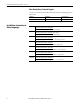
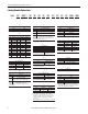
PowerFlex 700 Adjustable Frequency AC Drive – Frames 0…6 Table of Contents Catalog Number Explanation . . . . . . . . . . . . . . . . . . . . . . . . . . . . . . . . . . . . . . . . . . . . . 4 Step 1: Read the Precautions and General Information . . . . . . . . . . . . . . . . . . . . . 5 EMC Instructions . . . . . . . . . . . . . . . . . . . . . . . . . . . . . . . . . . . . . . . . . . . . . . . . . . . . . . . 7 Step 2: Mount the Drive. . . . . . . . . . . . . . . . . . . . . . . . . . . . . . . . .
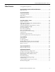
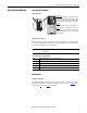
PowerFlex 700 Adjustable Frequency AC Drive – Frames 0…6 Catalog Number Explanation 20B a D 2P1 A 3 A Y N A E C 0 NN AD b c d e f g h i j k l m n a e j Drive HIM Comm Slot Code Type Code Operator Interface Code Network Type 20B PowerFlex 700 0 Blank Cover C ControlNet (Coax) 3 LCD Display, Full Numeric Keypad D DeviceNet b J♦ Remote (Panel Mount), IP66, NEMA/UL Type 12 Full Numeric LCD HIM E EtherNet/IP N None Voltage Rating K♦ Remote (Panel Mount),
PowerFlex 700 Adjustable Frequency AC Drive – Frames 0…6 Step 1: Read the Precautions Qualified Personnel and General Information ATTENTION: Only qualified personnel familiar with adjustable frequency AC drives and associated machinery must plan or implement the installation, startup and subsequent maintenance of the system. Failure to comply can result in personal injury and/or equipment damage.
PowerFlex 700 Adjustable Frequency AC Drive – Frames 0…6 Product Safety ATTENTION: An incorrectly applied or installed drive can result in component damage or a reduction in product life. Wiring or application errors, such as, undersizing the motor, incorrect or inadequate AC supply, or excessive ambient temperatures can result in malfunction of the system. ATTENTION: This drive contains ESD (Electrostatic Discharge) sensitive parts and assemblies.
PowerFlex 700 Adjustable Frequency AC Drive – Frames 0…6 EMC Instructions CE Conformity Conformity with the Low Voltage (LV) Directive and Electromagnetic Compatibility (EMC) Directive has been demonstrated by using harmonized European Norm (EN) standards published in the Official Journal of the European Communities. PowerFlex Drives(1) comply with the EN standards listed below when installed according to the information supplied in this publication and the Wiring & Grounding Guidelines Manual.
PowerFlex 700 Adjustable Frequency AC Drive – Frames 0…6 Essential Requirements for CE Compliance Conditions 1…6 listed below must be satisfied for PowerFlex drives to meet the requirements of EN61800-3. 1. Standard PowerFlex 700 CE compatible Drive. 2. Review important precautions/attention statements throughout this publication and the User Manual before installing the drive. 3. Grounding as described in this publication and the User Manual. 4.
PowerFlex 700 Adjustable Frequency AC Drive – Frames 0…6 Step 2: Mount the Drive Accessing the Terminals Opening the Cover POWER STS Lang Auto / Man 7 8 9 4 5 6 1 2 . 0 S.M.A.R.T. Exit Esc Sel Alt Exp Remove Jog 3 +/Param # PORT MOD NET A NET B CAUTION HOT surfaces can cause severe burns Frames 0…4 Locate the slot in the upper left corner. Slide the locking tab up and swing the cover open.
PowerFlex 700 Adjustable Frequency AC Drive – Frames 0…6 Table 2 - Acceptable Surrounding Air Temperature & Required Actions Enclosure Rating Temperature Range Drive IP20, NEMA/UL Type 1 (with Top Label) (1) 0…40 °C (0…104 °F) Frames 0…4, All Ratings 0…50 °C (0…122 °F) Frames 5…6, Most Ratings (2) IP20, NEMA/UL Type Open (Top Label Removed) (1) 0…50 °C (0…122 °F) Frames 0…6, Most Ratings (2) 0…45 °C (0…113 °F) 20BC072 Only IP00, NEMA/UL Type Open (Top Label & Vent Plate Removed) 0…50 °C (0…12
PowerFlex 700 Adjustable Frequency AC Drive – Frames 0…6 Dimensions Frames 0…3 – IP20, NEMA/UL Type 1 A D 15.0 (0.59) 5.8 (0.23) dia. Frame 0 Shown Weight (1) kg (lbs.) B E Frame C A 0 110.0 (4.33) 336.0 (13.23) 200.0 (7.87) 80.0 (3.15) 320.0 (12.60) 5.22 (11.5) 8.16 (18) 1 135.0 (5.31) 336.0 (13.23) 200.0 (7.87) 105.0 (4.13) 320.0 (12.60) 7.03 (15.5) 9.98 (22) 2 222.0 (8.74) 342.5 (13.48) 200.0 (7.87) 192.0 (7.56) 320.0 (12.60) 12.52 (27.6) 15.20 (33.5) 3 222.0 (8.74) 517.5 (20.37) 200.
PowerFlex 700 Adjustable Frequency AC Drive – Frames 0…6 Frame 4 – IP20, NEMA/UL Type 1 220.0 (8.66) 15.0 (0.59) 7.0 (0.28) dia. 192.0 (7.56) 201.7 (7.94) Dimensions are in millimeters and (inches) 758.8 (29.87) 738.2 (29.06) Frame 8.0 (0.31) 7.0 (0.28) x 3 Lifting Holes x 4 Approx. Weight (1) kg (lbs.) Drive 4 24.49 (54.0) Drive & Packaging 29.03 (64.0) (1) Weights include HIM and Standard I/O. 76.0 (2.99) 65.3 (2.57) 22.2 (0.87) Dia. 28.7 (1.13) Dia. 2 Places 47.0 (1.85) Dia. 2 Places 54.
PowerFlex 700 Adjustable Frequency AC Drive – Frames 0…6 Frame 5 – IP20, NEMA/UL Type 1 6.5 (0.26) 15.0 (0.59) 308.9 (12.16) 259.1 (10.20) 225.0 (8.86) 37.6 (1.48) 275.4 (10.84) 689.6 (27.15) 644.5 (25.37) 617.0 (24.29) 625.0 (24.61) CAUTION HOT surfaces can cause severe burns Junction Box 12.5 (0.49) Lifting Holes x 4 12.7 (0.50) Dia. 6.5 (0.26) Dimensions are in millimeters and (inches) Frame Approx. Weight (1) kg (lbs.) Drive Drive & Packaging 5 37.19 (82.0) 49.50 (109.
PowerFlex 700 Adjustable Frequency AC Drive – Frames 0…6 Frame 5 – IP54, NEMA Type 12 Standalone (400…690V drives only) 609.6 (24.00) 558.8 (22.00) 25.4 (1.00) 105.5 (4.15) 1543.0 ±1.5 (62.75 ±0.06) Air Outlet 1574.8 (62.00) DANGER REMOTE SOURCE(S) OF POWER. DISCONNECT ALL SOURCES OF POWER BEFORE OPENING THE DOOR. DANGER ELECTRICAL SHOCK HAZARD FROM ENERGY STORAGE CAPACITORS. VERIFY LOW VOLTAGE DISCHARGE BEFORE SERVICING. SEE INSTRUCTION MANUAL. 1061.5 (41.79) 140.0 (5.51) 16.8 (0.66) 13.5 (0.
PowerFlex 700 Adjustable Frequency AC Drive – Frames 0…6 Frame 5 – IP54, NEMA Type 12 Flange Mount (400…690V drives only) 500.0 (19.69) 219.5 (8.64) 196.5 (7.74) 11.0 (0.43) 12.7 (0.50) Dia. Lifting Holes x 4 478.0 (18.82) Air Outlet 1061.0 (41.77) 127.6 (5.02) SHLD 1039.0 (40.91) SHLD 449.6 (17.74) BRAKE TERMINAL RATINGS WIRE RANGE: 14-1/0 AWG (2.5-50 MM2) TORQUE: 32 IN-LB (3.6 N-M) STRIP LENGTH: 0.67 IN (17 MM) DANGER 300 VDC EXT PWR SPLY TERM (PS+, PS-) WIRE RANGE: 22-10 AWG (0.
PowerFlex 700 Adjustable Frequency AC Drive – Frames 0…6 Frame 5 – Flange Mount Cutout 4.00 (0.157) Dia. x 40, minimum 14 GA. (1.9) steel mounting surface. Deburr Pilot Holes and Drive Cutout. 10.0 (0.39) 458.0 (18.03) 1039.0 (40.91) 1026.5 (40.41) 948.5 (37.34) 870.5 (34.27) 792.5 (31.20) Cutout 714.5 (28.13) 1019.0 (40.12) 636.5 (25.06) 558.5 (21.99) 480.5 (18.92) 402.5 (15.85) 324.5 (12.78) 246.5 (9.71) Dimensions are in millimeters and (inches) 168.5 (6.63) 90.5 (3.56) 12.5 (0.49) 59.0 (2.
PowerFlex 700 Adjustable Frequency AC Drive – Frames 0…6 Frame 6 – IP20, NEMA/UL Type 1 403.9 (15.90) 360.6 (14.20) 300.0 (11.81) 49.6 (1.95) 8.5 (0.33) 275.5 (10.85) 18.0 (0.71) 850.0 (33.46) 825.0 (32.48) 126.3 (4.97) Old Style Junction Box 13.5 (0.53) Lifting Holes x 4 12.7 (0.50) Dia. 8.5 (0.33) New Style Junction Box Junction Box can be removed if drive is mounted in a cabinet Dimensions are in millimeters and (inches) Frame Approx. Weight (1) kg (lbs.) Drive Drive & Packaging 6 71.
PowerFlex 700 Adjustable Frequency AC Drive – Frames 0…6 Frame 6 – IP54, NEMA Type 12 Standalone (400…690V drives only) 24.1 (0.90) 123.6 (4.90) 711.3 (28.00) 663.1 (26.10) 1828.8 (72.00) 1795.2 (70.70) 1279.5 (50.40) 283.3 (11.20) 16.8 (0.66) 12.7 (0.50) Dia. Lifting Holes 13.5 (0.53) Dia. x 4 487.8 (19.20) Max. Mount with 0.50 in. UNC Grade 5 or higher screws or M12 Material Class 5.6 or higher screws. Use flat washer with each fastener 8.0 (0.
PowerFlex 700 Adjustable Frequency AC Drive – Frames 0…6 Frame 6 – IP54, NEMA Type 12 Flange Mount (400…690V drives only) 584.0 (23.00) 556.0 (21.90) 201.0 (7.90) 14.0 (0.60) 105.8 (4.17) 1100.0 (43.30) 1078.0 (42.40) 11.0 (0.43) BR2 22-12 AWG 5.3 IN-LB (0.6 N-M) WIRE STRIP PS+ PS- 763.3 (30.0) BR1 DC+ DC- U T1 V T2 W T3 PE PE R L1 S L2 T L3 137.2 127.3 (5.40) (5.00) OUTPUT USE 75C COPPER WIRE ONLY, TORQUE 52 IN-LB (6 N-M) Ground - M5 PEM Stud 5.5 (0.22) Dia. x 44 294.7 (11.60) 2.
PowerFlex 700 Adjustable Frequency AC Drive – Frames 0…6 Frame 6 – Flange Mount Cutout 4.00 (0.157) Dia. x 44, minimum 14 GA. (1.9) steel mounting surface. Deburr pilot holes and drive cutout. 12.0 (0.50) 532.0 (20.90) 1078.0 (42.40) 1043.0 (41.10) 971.0 (38.20) 899.0 (35.40) 827.0 (32.60) Cutout 755.0 (29.70) 1054.0 (41.5) 683.0 (26.90) 611.0 (24.10) 539.0 (21.20) 467.0 (18.40) 395.0 (15.60) 323.0 (12.70) 251.0 (9.90) 179.0 (7.00) 107.0 (4.20) 35.0 (1.40) 44.0 (1.70) 122.0 (4.80) 200.0 (7.90) 278.
PowerFlex 700 Adjustable Frequency AC Drive – Frames 0…6 Step 3: Wire the Drive – Power Special Considerations PowerFlex 700 drives are suitable for use on a circuit capable of delivering up to a maximum of 200,000 rms symmetrical amperes. ATTENTION: To guard against personal injury and/or equipment damage caused by improper fusing or circuit breaker selection, use only the recommended line fuses/circuit breakers specified on page 33.
PowerFlex 700 Adjustable Frequency AC Drive – Frames 0…6 ATTENTION: National Codes and standards (NEC, VDE, BSI etc.) and local codes outline provisions for safely installing electrical equipment. Installation must comply with specifications regarding wire types, conductor sizes, branch circuit protection and disconnect devices. Failure to do so can result in personal injury and/or equipment damage. EMC Compliance Refer to page 7 for details.
PowerFlex 700 Adjustable Frequency AC Drive – Frames 0…6 Shielded/Armored Cable Shielded cable contains all of the general benefits of multi-conductor cable with the added benefit of a copper braided shield that can contain much of the noise generated by a typical AC Drive. Strong consideration for shielded cable must be given in installations with sensitive equipment such as weigh scales, capacitive proximity switches and other devices that can be affected by electrical noise in the distribution system.
PowerFlex 700 Adjustable Frequency AC Drive – Frames 0…6 Single-Phase Input Power The PowerFlex 700 drive is typically used with a three-phase input supply. Singlephase operation is possible with output current derated by 50% (at maximum ambient temperature of 25 °C) of the three-phase ratings. Refer to tables 4 through 6. AC Input Phase Selection (Frames 5…6 Only) ATTENTION: To avoid a shock hazard, ensure that all power to the drive has been removed before performing the following.
PowerFlex 700 Adjustable Frequency AC Drive – Frames 0…6 Table 5 - 380…480 Volt Single-Phase AC Input Ratings 20BD1P1 Frame Drive Catalog Number 380…400V Single-Phase AC Input Three-Phase Output Hp Rating Input Amps V AC 0 0.25 0.7 0-460 Amps Drive Catalog Number 0.6 20BC1P3 Three-Phase Output Temp. Frame 480V Single-Phase AC Input kW Input Rating Amps V AC Amps °C 0 0.2 0-400 0.7 25 1 20BD2P1 0 0.5 1.4 0-460 1.1 20BC2P1 0 0.4 1.6 0-400 1.1 25 20BD3P4 0 1 2.
PowerFlex 700 Adjustable Frequency AC Drive – Frames 0…6 Selecting/Verifying Fan Voltage (Frames 5…6 Only) ATTENTION: To avoid a shock hazard, ensure that all power to the drive has been removed before performing the following. IMPORTANT Frames 5 & 6 utilize a fan transformer to power the internal fan(s). This transformer is sized specifically for the internal fan(s) and must not be used to power other circuitry.
PowerFlex 700 Adjustable Frequency AC Drive – Frames 0…6 Auxiliary Control Power Supply If desired, an auxiliary control power supply can be used with certain drives to keep the control logic up when the main AC power is removed. An auxiliary control power supply can only be used with: • 400/480 and 600/690 Volt drives with Vector Control (15th position of the catalog number string equals “C,” or “D”).
PowerFlex 700 Adjustable Frequency AC Drive – Frames 0…6 Power Terminal Blocks Wire Size Range (2) No. Name ➊ Power Terminal Block ➋ SHLD Description Maximum Minimum Maximum Recommended Input power and motor connections 4.0 mm2 (12 AWG) 0.5 mm2 (22 AWG) 1.7 N•m (15 lb•in) 0.8 N•m (7 lb•in) 2 Input power and motor connections 10.0 mm2 (8 AWG) 0.8 mm2 (18 AWG) 1.7 N•m (15 lb•in) 1.4 N•m (12 lb•in) 3 Input power and motor connections 25.0 mm2 (3 AWG) 2.5 mm2 (14 AWG) 3.
PowerFlex 700 Adjustable Frequency AC Drive – Frames 0…6 Typical Terminal Block Location ➌ ! DANGER Use 75C Wire Only Optional Communications Module Optional Communications Module #10-#14 AWG Torque to 7 in-lbs BR1 ➌ DC– PE WIRE STRIP 75C Cu Wire 6 AWG [10MM2] Max. 12 IN. LBS. } TORQUE 1.4 N-M BR1 B U/T1 V/T2 W/T3 POWER DC+ CONTROL BR2 PE B PE R/L1 S/L2 T/L3 PE A V/T2 ➊ ➌ S/L2 T/L3 ➊ SHLD ➋ SHLD ➊ Frames 0…1 ➋ WIRE STRIP BR1 BR2 75C Cu Wire 6 AWG [10MM2] Max. 12 IN. LBS. 1.
PowerFlex 700 Adjustable Frequency AC Drive – Frames 0…6 Terminal Block Details Frame Power Terminal Blocks 0…1 Notes: Shaded BR1 & BR2 Terminals are only present on drives ordered with the Brake Option. ➊Precharge Resistor Fuse – DCT12-2 (DC input drives w/precharge only) ➋M8 Stud (All Terminals) Max. Lug Width = 25.4 mm (1 in.) ➌M8 Stud (All Terminals) Max. Lug Width = 31.8 mm (1.25 in.
PowerFlex 700 Adjustable Frequency AC Drive – Frames 0…6 Terminal Description Notes BR1 BR2 DC Brake (+) DC Brake (–) DB Resistor Connection - Important: Only one DB resistor can be used with Frames 0…3. Connecting an internal & external resistor could cause damage. Twisted pair wiring must be used from these terminals to the resistor. Wiring must be routed separately from other cabling. DC+ DC– DC Bus (+) DC Bus (–) DC Input/Brake Connections (chopper and resistor).
PowerFlex 700 Adjustable Frequency AC Drive – Frames 0…6 Shield Termination Shield termination at “SHLD” provides a grounding point for the motor cable shield. The motor cable shield must be connected to this terminal on the drive (drive end) and the motor frame (motor end). A shield terminating cable gland can also be used. When shielded cable is used for control and signal wiring, the shield must be grounded at the source end only, not at the drive end.
PowerFlex 700 Adjustable Frequency AC Drive – Frames 0…6 Drive, Fuse & Circuit Breaker Ratings The PowerFlex 700 can be installed with input fuses or an input circuit breaker. National and local industrial safety regulations and/or electrical codes can determine additional requirements for these installations. ATTENTION: The PowerFlex 700 does not provide branch short circuit protection.
PowerFlex 700 Adjustable Frequency AC Drive – Frames 0…6 Drive Catalog Number 20BB2P2 20BB4P2 20BB6P8 20BB9P6 20BB015 20BB022 20BB028 20BB042 20BB052 20BB070 20BB080 20BB104 (12) Frame 208 Volt AC Input Protection Devices 0 0 1 1 1 1 2 3 3 4 4 5 20BB130 5 (12) 20BB154 6 (12) 20BB192 6 (12) 20BB260 6 (12) Hp Rating PWM Temp. Input Freq. (11) Ratings Output Amps ND 0.5 1 2 3 5 7.5 10 15 20 25 30 40 – 50 – 60 – 75 – 100 – kHz 4 4 4 4 4 4 4 4 4 4 4 4 4 4 4 4 4 4 4 2 2 Cont. 2.5 4.8 7.8 11 17.
PowerFlex 700 Adjustable Frequency AC Drive – Frames 0…6 400 Volt AC Input Protection Devices kW Rating Frame Drive Catalog Number PWM Freq. Temp. Input Ratings Motor Circuit Circuit Dual Element Non-Time Delay Breaker Protector 140M Motor Protector with Adjustable Current (3) (4) Time Delay Fuse Fuse Range (5)(6) Output Amps Available Catalog Numbers 140… (7) Min. Enclosure Vol. (in.
PowerFlex 700 Adjustable Frequency AC Drive – Frames 0…6 480 Volt AC Input Protection Devices Hp Rating Frame Drive Catalog Number PWM Freq. Temp. Input Ratings Motor Circuit Circuit Dual Element Non-Time Delay Breaker Protector 140M Motor Protector with Adjustable Current (3) (4) Time Delay Fuse Fuse Range (5)(6) Output Amps °C Amps kVA Cont. 1 Min. 3 Sec. Min. (1) Max. (2) Min. (1) Max. (2) Max. (8) Max. (8) Available Catalog Numbers 140… (7) Min. Enclosure Vol. (in.3) (14) 20BD1P1 0 0.5 0.
PowerFlex 700 Adjustable Frequency AC Drive – Frames 0…6 600 Volt AC Input Protection Devices (13) Frame Drive Catalog Number Hp Rating PWM Temp. Input Freq. (11) Ratings ND HD kHz °C Dual Element Time Delay Fuse Output Amps Circuit Motor Non-Time Delay Breaker Circuit 140M Motor Protector with Adjustable Current (3) Fuse Protector (4) Range (5)(6) Amps kVA Cont. 1 Min. 3 Sec. Min. (1) Max. (2) Min. (1) Max. (2) Max. (8) Max. (8) Available Catalog Numbers 140… (7) Min. Enclosure Vol. (in.
PowerFlex 700 Adjustable Frequency AC Drive – Frames 0…6 Notes (1) Minimum protection device size is the lowest rated device that supplies maximum protection without nuisance tripping. (2) Maximum protection device size is the highest rated device that supplies drive protection. For US NEC, minimum size is 125% of motor FLA. Ratings shown are maximum. (3) Circuit Breaker - inverse time breaker. For US NEC, minimum size is 125% of motor FLA. Ratings shown are maximum.
PowerFlex 700 Adjustable Frequency AC Drive – Frames 0…6 540 Volt DC Input Protection Devices PWM Freq. Temp. DC Input Ratings Output Amps ND HD kHz °C Amps Cont. 1 Min. 3 Sec. Fuse Non-Time Delay Fuse (2) (11) Drive Catalog Number Frame (1) kW Rating 20BC1P3 0 0.37 0.25 4 50 1.3 1.3 1.4 1.9 3 JKS-3 20BC2P1 0 0.75 0.55 4 50 2.1 2.1 2.4 3.2 6 JKS-6 20BC3P5 0 1.5 0.75 4 50 3.7 3.5 4.5 6 8 JKS-8 20BC5P0 0 2.2 1.5 4 50 5.3 5 5.5 7.
PowerFlex 700 Adjustable Frequency AC Drive – Frames 0…6 Hp Rating PWM Freq. Temp. Frame 650 Volt DC Input Protection Devices (1) DC Input Ratings Output Amps ND HD kHz °C Amps Cont. 1 Min. 3 Sec. Fuse Non-Time Delay Fuse (2) (11) 0 0.5 0.33 4 50 1.0 1.1 1.2 1.6 3 JKS-3 0 1 0.75 4 50 1.9 2.1 2.4 3.2 6 JKS-6 20BD3P4 0 2 1.5 4 50 3.0 3.4 4.5 6.0 6 JKS-6 20BD5P0 0 3 2 4 50 4.5 5.0 5.5 7.5 10 JKS-10 20BD8P0 0 5 3 4 50 8.1 8.0 8.
PowerFlex 700 Adjustable Frequency AC Drive – Frames 0…6 Drive Catalog Number 20BW052 (3) 20BW098 (3) 20BW142 (3) Frame 932 Volt DC Input Protection Devices kW Rating PWM Freq. Temp. DC Input (1) Ratings Output Amps ND HD kHz °C Amps Cont. 1 Min. 3 Sec. Fuse Non-Time Delay Fuse (2) (11) 5 45 – 2 50 (4) 58.2 52 57 78 100 170M3691 – 37.5 2 50 (4) 46.9 46 69 92 100 170M3691 90 – 2 50 (4) 110.7 98 108 127 160 170M3693 – 75 2 50 (4) 92.
PowerFlex 700 Adjustable Frequency AC Drive – Frames 0…6 Using Input/Output Contactors Input Contactor Precautions ATTENTION: A contactor or other device that routinely disconnects and reapplies the AC line to the drive to start and stop the motor can cause drive hardware damage. The drive is designed to use control input signals that start and stop the motor. If an input device is used, operation must not exceed one cycle per minute or drive damage occurs.
PowerFlex 700 Adjustable Frequency AC Drive – Frames 0…6 Disconnecting MOVs and Common Mode Capacitors The Powerflex 700 drive contains protective MOVs and Common Mode Capacitors referenced to ground (see below). To guard against unstable operation and/or damage, the drive must be properly configured as shown in Table 9 on page 44.
PowerFlex 700 Adjustable Frequency AC Drive – Frames 0…6 Table 9 - Recommended Power Jumper Configurations Power Source Type (1) MOV/Input Filter Caps (2) DC Bus Common Mode Caps Solid Ground Connected Connected • • • • Disconnected Disconnected • Helps avoid severe equipment damage when ground fault occurs.
PowerFlex 700 Adjustable Frequency AC Drive – Frames 0…6 Drive Identification Refer to the drive nameplate and locate Voltage Code Series Current Rating the “Voltage Code,” “Current Rating,” UL Type “Frame,” and “UL Type” (Frames 5…6). Cat No. 20B D xxx x x xxxxxxx Use this information to locate the Series: B 400V 480V I/O: 24VAC/DC (Standard) proper procedure in the following Normal Duty Power xxx kW xxx kW Original Firmware V. x.xxx Heavy Duty Power xxx kW xxx kW Input: 3 Phase, 47-63Hz tables.
PowerFlex 700 Adjustable Frequency AC Drive – Frames 0…6 Current Rating Voltage Code Frame Factory Default Jumper Settings MOV/Input DC Bus Common Filter Caps (1) (2) Mode Caps Power Source Type 3…4 All Drives (continued) B…E All PE_MOV Installed PE-CAP Installed Solid Ground • Verify that jumpers are installed at the “PE_CAP” and “PE_MOV” locations. Non-Solid Ground MOV • Remove jumpers at the “PE_CAP” and “PE_MOV” locations.
PowerFlex 700 Adjustable Frequency AC Drive – Frames 0…6 Voltage Code 5 IP20, NEMA/UL Type 1 and Open Drives (continued) C F W Current Rating Frame Factory Default Jumper Settings 140 052 060 MOV/Input Filter Caps (1) (2) DC Bus Common Mode Caps Two green/yellow wires connected to the Power Terminal Block rail Green/yellow wire to CM Cap Board is connected to ground Optional Communications Module MOV 300 VDC EXT PWR SPLY TERM (PS+, PS-) POWER TERMINAL RATINGS WIRE RANGE: 14-1/0 AWG (2.
PowerFlex 700 Adjustable Frequency AC Drive – Frames 0…6 Voltage Code 5 IP54, NEMA Type 12 Drives C D P R Current Rating Frame Factory Default Jumper Settings All MOV/Input Filter Caps (1) (2) DC Bus Common Mode Caps Two green/yellow wires connected to chassis ground CM Cap Older Drives Green/yellow wire is connected to ground CM Cap - Newer Drives SHLD SHLD MOV BRAKE TERMINAL RATINGS WIRE RANGE: 14-1/0 AWG (2.5-50 MM2) TORQUE: 32 IN-LB (3.6 N-M) STRIP LENGTH: 0.
PowerFlex 700 Adjustable Frequency AC Drive – Frames 0…6 Voltage Code 5 IP54, NEMA Type 12 Drives (continued) E F T W Current Rating Frame Factory Default Jumper Settings All MOV/Input Filter Caps (1) (2) Two green/yellow wires connected to chassis ground DC Bus Common Mode Caps Green/yellow wire to CM Cap Board is connected to ground SHLD SHLD CM Cap MOV BRAKE TERMINAL RATINGS WIRE RANGE: 14-1/0 AWG (2.5-50 MM2) TORQUE: 32 IN-LB (3.6 N-M) STRIP LENGTH: 0.
PowerFlex 700 Adjustable Frequency AC Drive – Frames 0…6 Voltage Code 6 IP20, NEMA/UL Type 1 and Open Drives B C D H J N P R Current Rating Frame Factory Default Jumper Settings All MOV/Input Filter Caps (1) (2) DC Bus Common Mode Caps Two green/yellow wires connected to Power Terminal Block “PE” Green/yellow wire to CM Cap Board is connected to Power Terminal Block “PE” DO NOT REMOVE WIRE STRIP PS+ PS– MOV BR2 BR1 DC+ DC– USE 75 C COPPER WIRE ONLY, TORQUE 52 IN-LB (6 N-M) Input Filter C
PowerFlex 700 Adjustable Frequency AC Drive – Frames 0…6 Voltage Code 6 IP20, NEMA/UL Type 1 and Open Drives (continued) E F T W Current Rating Frame Factory Default Jumper Settings All MOV/Input Filter Caps (1) (2) DC Bus Common Mode Caps Green/yellow wire to CM Cap Board is connected to Power Terminal Block “PE” Two green/yellow wires connected to Power Terminal Block “PE” and chassis Input Filter Cap Optional Communications Module DO NOT REMOVE Solid Ground 1.
PowerFlex 700 Adjustable Frequency AC Drive – Frames 0…6 Important points to remember about I/O wiring: Step 4: I/O Wiring • Use Copper wire only. Wire gauge requirements and recommendations are based on 75 degrees C. Do not reduce wire gauge when using higher temperature wire. • Wire with an insulation rating of 600V or greater is recommended. • Separate control and signal wires from power wires by at least 0.3 meters (1 foot).
PowerFlex 700 Adjustable Frequency AC Drive – Frames 0…6 I/O Terminals The figure below shows the I/O Control Cassette and terminal block locations. The cassette provides a mounting point for the various PowerFlex 700 I/O options. To remove the cassette, follow the steps below. Cassette removal is similar for all frames (Frame 0 drive shown). Step Description A Disconnect the two cable connectors shown below. B Loosen the two screw latches shown below. C Slide the cassette out.
PowerFlex 700 Adjustable Frequency AC Drive – Frames 0…6 Vector Control Option I/O Terminal Designations No. Signal 1 16 32 1 Analog In 1 (–) (1) 2 Analog In 1 (+) (1) 3 Analog In 2 (–) (1) 4 Analog In 2 (+) (1) 5 Factory Default Description Related Param. (4) Isolated (5), bipolar, differential, ±10V/0-20 mA, 11 bit & sign. For 0-20 mA, a jumper must be installed at terminals 17 & 18 (or 19 & 20). 88k ohm input impedance when configured for volt. & 95.
PowerFlex 700 Adjustable Frequency AC Drive – Frames 0…6 Standard Control Option I/O Terminal Designations No. Signal 1 16 Factory Default Description Related Param. (2) Isolated (3), bipolar, differential, ±10V, 11 bit & sign, 88k ohm input impedance. 320 327 (2) Isolated (4), bipolar, differential, ±10V, 11 bit & sign, 88k ohm input impedance. 1 Anlg Volts In 1 (–) 2 Anlg Volts In 1 (+) 3 Anlg Volts In 2 (–) 4 Anlg Volts In 2 (+) 5 Pot Common – For (+) and (–) 10V pot references.
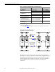
PowerFlex 700 Adjustable Frequency AC Drive – Frames 0…6 I/O Wiring Examples Input/Output Connection Example Potentiometer Unipolar Speed Reference (1) 10k Ohm Pot.
PowerFlex 700 Adjustable Frequency AC Drive – Frames 0…6 Input/Output Connection Example 2-Wire Control Reversing(1) External supply (I/O Board dependent) Required Parameter Changes Neutral/ Common 115V/ +24V 25 27 28 Run Fwd. • Set Digital Input:#1: Parameter 361 = “8, Run Forward” • Set Digital Input #2: Parameter 362 = “9, Run Reverse” Run Rev. 3-Wire Control Internal supply 24 25 26 27 28 • No Changes Required Stop Start 3-Wire Control External supply (I/O Board dependent).
PowerFlex 700 Adjustable Frequency AC Drive – Frames 0…6 Encoder Interface Option (Vector Control Only) Encoder Terminal Designations See “Detail” on page 53 8 1 No. Description 8 +12V (1) DC Power 7 +12V (1) 6 Encoder Z (NOT) 5 Encoder Z 4 Encoder B (NOT) 3 Encoder B 2 Encoder A (NOT) 1 Encoder A Internal power source 250 mA. DC Return (Common) Pulse, marker or registration input. (2) Quadrature B input. Single channel or quadrature A input.
PowerFlex 700 Adjustable Frequency AC Drive – Frames 0…6 Sample Encoder Wiring Connection Example Encoder Signal –Single-Ended, Dual Channel (2) 7 Common 6 5 Connection Example + 8 I/O Encoder Power –External Power Source +12V DC (250 mA) to SHLD (1) 4 Common I/O Encoder Power –Internal Drive Power Internal (drive) 12V DC, 250mA (1) to SHLD (1) External Power Supply 3 2 1 to Power Supply Common 8 7 6 5 4 Z NOT to SHLD (1) Z B NOT Encoder Signal –Differential, Dual Channel to SHLD (1
PowerFlex 700 Adjustable Frequency AC Drive – Frames 0…6 Changing Speed Sources The selection of the active Speed Reference can be made through digital inputs, DPI command, jog button or Auto/Manual HIM operation. Torque Reference Source The torque reference is normally supplied by an analog input or network reference. Switching between available sources while the drive is running is not available.
PowerFlex 700 Adjustable Frequency AC Drive – Frames 0…6 PLC = Auto, Terminal Block = Manual A process is run by a PLC when in Auto mode and requires manual control from an analog potentiometer wired to the drive terminal block. The auto speed reference is issued by the PLC through a communications module installed in the drive. Since the internal communications is designated as Port 5, [Speed Ref A Sel] is set to “DPI Port 5” with the drive running from the Auto source.
PowerFlex 700 Adjustable Frequency AC Drive – Frames 0…6 • Attain Manual Control – Close the digital input. With the input closed, the speed command comes from the HIM. • Release to Auto Control – Open the digital input. With the input open, the speed command returns to the PLC. Auto/Manual Notes 1. Manual control is exclusive. If a HIM or terminal block takes manual control, no other device can take manual control until the controlling device releases manual control. 2.
PowerFlex 700 Adjustable Frequency AC Drive – Frames 0…6 IMPORTANT When power is first applied, the HIM can require approximately 5 seconds until commands are recognized (including the Stop key). An explanation of the LED indicators can be found on page 75. 5. Apply AC power and control voltages to the drive. If any of the six digital inputs are configured to “Stop – CF” (CF = Clear Fault) or “Enable,” verify that signals are present or reconfigure [Digital Inx Sel], parameters 361…366.
PowerFlex 700 Adjustable Frequency AC Drive – Frames 0…6 First Powerup Menu Structure English? Français? Español? Italiano? Deutsch? Português? Nederlands? Not Selected Main Menu: Diagnostics Parameter Device Select Memory Storage Start-Up Preferences PowerFlex 700 Start-Up Startup consists of several steps to configure a drive for basic applications. PowerFlex 700 Start-Up Make a selection 1. SMART 2. Basic 3. Detailed 4. More info PowerFlex 700 Start-Up Complete these steps in order: 1.
PowerFlex 700 Adjustable Frequency AC Drive – Frames 0…6 Supplemental Information Using PowerFlex Drives w/Regen Units If a Regenerative unit (for example, 1336 REGEN) is used as a bus supply or brake, the common mode capacitors must be disconnected as described on page 43.
PowerFlex 700 Adjustable Frequency AC Drive – Frames 0…6 Human Interface Module (HIM) Overview LCD Display Elements Display Description F-> Power Loss Auto 0.0 Hz Direction⎥ Drive Status⎥ Alarm⎥ Auto/Man⎥ Information Commanded or Output Frequency Main Menu: Diagnostics Parameter Device Select Programming / Monitoring / Troubleshooting Human Interface Module (HIM) Key Functions Key Description Esc Exit a menu, cancel a change to a parameter value, or acknowledge a fault/alarm.
PowerFlex 700 Adjustable Frequency AC Drive – Frames 0…6 ALT Functions To use an ALT function, start at the Main Menu and press the ALT key, release it, then press the programming key associated with one of the following functions: ALT Key then ALT Function Function Description Esc S.M.A.R.T. Displays the S.M.A.R.T. screen. This function allows the drive parameter values to be quickly programed by directly accessing the most frequently used drive functions.
PowerFlex 700 Adjustable Frequency AC Drive – Frames 0…6 • Assisted Start Up Three levels of Assisted Start Up (Basic, Detailed and Application) aid the user in commissioning the drive asking simple Yes/No or “Enter Data” questions. The user is guided through the Start Up to reduce the amount of time necessary to get the drive “up and running.
PowerFlex 700 Adjustable Frequency AC Drive – Frames 0…6 Start Up Menu Done / Exit Basic Start-Up Continue Start Over Intro Selection: 1. SMART 2. Basic 3. Detailed 4.
PowerFlex 700 Adjustable Frequency AC Drive – Frames 0…6 Running an Assisted Start Up IMPORTANT This start-up routine requires an LCD HIM. The Assisted start-up routine prompts you to input required information. Access Assisted Start Up by selecting “Start Up” from the Main Menu. To perform an Assisted Start-Up Step Key(s) Example LCD Displays 1. In the Main Menu, press the Up Arrow or Down Arrow to scroll to “Start Up”. 2. Press Enter. F-> Stopped Auto 0.
PowerFlex 700 Adjustable Frequency AC Drive – Frames 0…6 Common I/O Programming Changes Your application needs may require changing parameters from their factory default settings. Speed Reference A Change Speed Reference A from Analog In 2 to Analog In 1 to connect an external potentiometer. 1. Set Param. 090 [Speed Ref A Sel] to option 1 “Analog In 1” This sets the speed reference input to I/O terminals 1 & 2. For 4…20 mA operation, a jumper must be placed between terminals 17 & 18. 2. Set Param.
PowerFlex 700 Adjustable Frequency AC Drive – Frames 0…6 Troubleshooting For a complete listing of Faults and Alarms, refer to the PowerFlex 700 User Manual, publication 20B-UM002. Fault No. Type(1) Table 10 - Abbreviated Fault Listing Auxiliary Input 2 ➀ Decel Inhibit 24 ➂ The drive is not following a commanded Description Action Auxiliary input interlock is open. Check remote wiring. deceleration because it is attempting to limit bus voltage.
PowerFlex 700 Adjustable Frequency AC Drive – Frames 0…6 Alarm No. Type(1) Table 11 - Abbreviated Alarm Listing Dig In ConflictA 17 ➁ Digital input functions are in conflict. Combinations marked with a “ ” cause an alarm. Description Acc2/Dec2 Accel 2 Decel 2 Jog 1/2 Jog Fwd Jog Rev Fwd/Rev Acc2/Dec2 Accel 2 Decel 2 Jog 1/2 Jog Fwd Jog Rev Fwd/Rev Dig In ConflictB 18 ➁ A digital Start input has been configured without a Stop input or other functions are in conflict.
PowerFlex 700 Adjustable Frequency AC Drive – Frames 0…6 Common Symptoms and Corrective Actions Drive does not Start from Start or Run Inputs wired to the terminal block. Cause(s) Indication Corrective Action Drive is Faulted Flashing red status light Clear fault. None Wire inputs correctly and/or install jumper. Incorrect digital input programming. None • Mutually exclusive choices have been made (i.e., Jog and Jog Forward). • 2 wire and 3 wire programming can be conflicting.
PowerFlex 700 Adjustable Frequency AC Drive – Frames 0…6 Motor and/or drive do not accelerate to commanded speed. Cause(s) Indication Corrective Action Acceleration time is excessive. None Reprogram [Accel Time x]. Excess load or short acceleration times force the drive into current limit, slowing or stopping acceleration. None Check [Drive Status 2], bit 10 to see if the drive is in Current Limit. Remove excess load or reprogram [Accel Time x]. Speed command source or value is not as expected.
PowerFlex 700 Adjustable Frequency AC Drive – Frames 0…6 Manually Clearing Faults Step 1. Press Esc to acknowledge the fault. The fault information is removed so that you can use the Human Interface Module (HIM). 2. Address the condition that caused the fault. The cause must be corrected before the fault can be cleared. 3. After corrective action has been taken, clear the fault by one of these methods: • Press Stop • Cycle drive power • Set parameter 240 [Fault Clear] to “1.
PowerFlex 700 Adjustable Frequency AC Drive – Frames 0…6 Notes: Rockwell Automation Publication 20B-IN019E-EN-P - July 2013 77
Rockwell Automation Support Rockwell Automation provides technical information on the Web to assist you in using its products. At http://www.rockwellautomation.com/support, you can find technical manuals, technical and application notes, sample code and links to software service packs, and a MySupport feature that you can customize to make the best use of these tools. You can also visit our Knowledgebase at http://www.rockwellautomation.