
Manual

Publication 20B-IN021B-EN-P
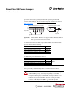
10 PowerFlex 700 Power Jumpers
Frame
Voltage
Code
Current
Rating
Factory Default Jumper Settings
Power Source TypeMOV
(1)
DC Bus Common
Mode Caps &
Input Filter Cap
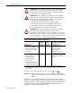
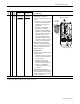
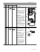
7 All All A green/yellow
wire connected
to
Power Terminal
Block “PE”
Not Applicable Solid Ground
• The green/yellow MOV jumper wire
should be connected to “PE.”
Non-Solid Ground
• The green/yellow MOV jumper wire
should be insulated from ground. If
necessary, remove the wire from “PE”
and insulate/secure it to guard against
unintentional contact with chassis or
components.
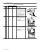
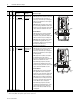
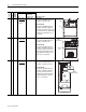
8…9 All All A green/yellow
wire connected
to
the “PE” bus bar
Not Applicable Solid Ground
• The green/yellow MOV jumper wire
should be connected to “PE.”
Non-Solid Ground
• The green/yellow MOV jumper wire
should be insulated from ground. If
necessary, remove the wire from the
“PE” bus bar and insulate/secure it to
guard against unintentional contact
with chassis or components.
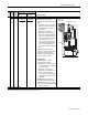
10 All All A green/yellow
wire connected
to
chassis
Not Applicable Solid Ground
• The green/yellow MOV jumper wire
should be connected to the chassis.
Non-Solid Ground
• The green/yellow MOV jumper wire
should be insulated from ground. If
necessary, remove the wire and
insulate/secure both ends to guard
against unintentional contact with
chassis or components.
(1)
AC input drives only. MOV’s do not exist on DC input drives.
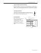
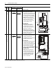
+DC
USE 75
°
COPPER WIRE ONLY
TORQUE LARGE TERMINALS TO 10 N-m (87LB-IN)
-DC PE PE R-L1 T-L3
RISK OF SHOCK
REPLACE AFTER
SERVICING
!
DANGER
U-M1 V-M2 W-M3S-L2
TB11
25 AMPERES RMS
MAXIMUM
ALLEN-BRADLEY
MADE IN U.S.A.
PE
MOV
PE
V
W
U
R S T DC-DC+
GND
MOV
(under boards)
PE Bus
Bar
120
IN1
120
IN2
3
4
5
6
TB10
8 AMPERES RMS
MAXIMUM
GND
RISK OF SHOCK
REPLACE AFTER
SERVICING
!
DANGER
MOV
Jumper Wire
Converter Section