
Owner manual

34 Rockwell Automation Publication 20B-IN026B-EN-P - July 2013
Chapter 2 Basic Component Removal Procedures
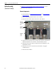
Busbar Assembly
(Converter Assembly)
See Chapter 1 - Component Diagrams and Torque Specifications to locate
components in these instructions.
Remove Components
1. Read and follow the Safety Precautions on page 11 and Important Initial
Steps on page 12.
2. Remove safety shields and enclosure covers as needed.
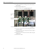
3. Remove the DC Choke cables from the DC+/DC- Busbars.
4. Label the wires and remove the screw that secures the three wires from the
Snubber Board DC1 screw terminal to the DC+ Busbar, and save.
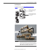
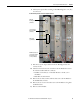
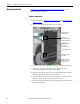
5. Remove the three bolts, washers, and nuts that secure the Busbar to each
SCR Module, and save.
6. Remove the two set screw nuts that secure the busbar to the glastic
standoffs and save.
7. Remove the DC+ Busbar.
Wires from
Snubber Board
Screw Terminal
(DC1)
Set Screw
Nuts (2) for
Glastic Standoffs
Bolt, Washer
and Nut
(3 each)