
Owner manual

Rockwell Automation Publication 20B-IN026B-EN-P - July 2013 27
Basic Component Removal Procedures Chapter 2
Transitional Busbar
Assembly
(Inverter Assembly)
See Chapter 1 - Component Diagrams and Torque Specifications to locate
components in these instructions.
Remove Components
1. Read and follow the Safety Precautions on page 11 and Important Initial
Steps on page 12.
2. Remove safety shields and enclosure covers as needed.
3. Remove the Main Control panel. See Main Control Panel (Inverter
Assembly) on page 22.
4. Remove the Stacking Panel. See Stacking Panel (Inverter Assembly) on
page 24.
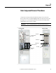
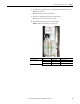
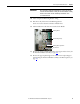
5. Locate the Transitional Busbar assembly.
IMPORTANT
The instructions detailed in this section describe how to remove the
Transitional Busbar assembly as a single unit.
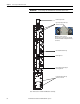
DC Choke Output Cables Location
Transitional Busbar Assembly
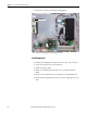
Balancing Resistor
Side Standoffs and Brackets (6)
IGBT Snubber Components (3)
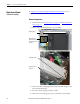
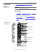
Upper and Lower Capbus Support
Connecting Brackets
Lower Capbus Support
Upper Capbus Support
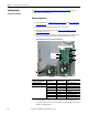
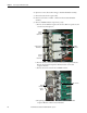
Transitional Busbar Assembly
(4 pcs: DC+ Busbar, DC- Busbar,
Upper Capbus Support,
Lower Capbus Support)