
Owner manual

Rockwell Automation Publication 20B-IN026B-EN-P - July 2013 15
Component Diagrams and Torque Specifications Chapter 1
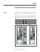
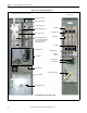
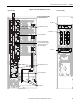
Figure 2 - Frame 10 Assembly Busbar Locations
R
L1
S
L2
T
L3
Inverter Assembly Converter Assembly
Motor Busbars
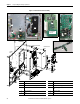
Lower DC Bus Capacitors (8)
Inverter Assembly Shown With
Stacking Panel Removed
Upper DC Bus Capacitors (18)
Lower Capbus Support
Transitional Busbar Assembly
(4 pcs: DC+ Busbar, DC- Busbar,
Upper Capbus Support, and
Lower Capbus Support)
Upper Capbus Support
AC Busbars (3)
DC- Busbar
DC+ Busbar
U
W
V