Installation Instructions PowerFlex 700 Drives - Frame 10 Components Replacement
Important User Information Read this document and the documents listed in the additional resources section about installation, configuration, and operation of this equipment before you install, configure, operate, or maintain this product. Users are required to familiarize themselves with installation and wiring instructions in addition to requirements of all applicable codes, laws, and standards.
Table of Contents Preface Introduction. . . . . . . . . . . . . . . . . . . . . . . . . . . . . . . . . . . . . . . . . . . . . . . . . . . . . . . 7 Component Kits . . . . . . . . . . . . . . . . . . . . . . . . . . . . . . . . . . . . . . . . . . . . . . . . . . . 8 Recommended Tools . . . . . . . . . . . . . . . . . . . . . . . . . . . . . . . . . . . . . . . . . . . . . 10 Safety Precautions. . . . . . . . . . . . . . . . . . . . . . . . . . . . . . . . . . . . . . . . . . . . . . . .
Table of Contents 24V Power Supply Board. . . . . . . . . . . . . . . . . . . . . . . . . . . . . . . . . . . . . . . . . . Remove Components . . . . . . . . . . . . . . . . . . . . . . . . . . . . . . . . . . . . . . . . . Install Components. . . . . . . . . . . . . . . . . . . . . . . . . . . . . . . . . . . . . . . . . . . DC Bus Filter Board . . . . . . . . . . . . . . . . . . . . . . . . . . . . . . . . . . . . . . . . . . . . . . Remove Components . . . . . . . . . . . . . . . . . . . . . . . . . . .
Table of Contents Precharge Board . . . . . . . . . . . . . . . . . . . . . . . . . . . . . . . . . . . . . . . . . . . . . . . . . Remove Components. . . . . . . . . . . . . . . . . . . . . . . . . . . . . . . . . . . . . . . . . Install Components . . . . . . . . . . . . . . . . . . . . . . . . . . . . . . . . . . . . . . . . . . Snubber Resistors . . . . . . . . . . . . . . . . . . . . . . . . . . . . . . . . . . . . . . . . . . . . . . . . Remove Components. . . . . . . . . . . . . . . . . . . . . . .
Table of Contents Notes: 6 Rockwell Automation Publication 20B-IN026B-EN-P - July 2013
Preface This publication provides guidelines for replacing the major components in the PowerFlex 700 Frame 10 drive. Introduction The PowerFlex 700 Frame 10 drive is available in AC input and DC input. AC input drives ship as two separate units (inverter and converter) that must be connected when installed on site, and DC input drives ship as one unit (inverter). See Overview on page 13 for more details.
Preface Component Kits All kits include necessary components, Electrostatic Discharge (ESD) wrist strap, hardware (if required), and thermal grease (if required).
Preface Description Enclosure Options Converter Gasket Kit Inverter Gasket Kit Kit Catalog No. Notes SK-G1-GASKET2-F10 SK-G1-GASKET1-F10 For AC input only (1) For DC input only (2) (1) AC input applies to PowerFlex 700 catalog numbers beginning with 20BC875 or 20BD875. (2) DC input applies to PowerFlex 700 catalog numbers beginning with 20BH875 or 20BJ875.
Preface Recommended Tools The following list of tools is provided for your reference to disassemble and reassemble the drive and components. This list may not include all tools for your situation. Not all tools are needed for some components. See specific sections for details.
Preface Safety Precautions Follow all the precautions and general installation requirements provided in the PowerFlex 700 Frame 7-10 Installation Instructions (publication 20B-IN014) and the PowerFlex 700 User Manual (publication 20B-UM002) along with those included here. ATTENTION: To avoid an electric shock hazard, ensure that all power has been removed before proceeding. In addition, before servicing, verify that the voltage on the bus capacitors has discharged.
Preface ATTENTION: This assembly contains parts and sub-assemblies that are sensitive to electrostatic discharge. Static control precautions are required when servicing this assembly. Component damage may result if you ignore electrostatic discharge control procedures. If you are not familiar with static control procedures, reference Allen-Bradley Guarding Against Electrostatic Damage (publication 8000-4.5.2) or any other applicable ESD protection handbook.
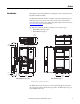
Chapter 1 Component Diagrams and Torque Specifications Overview This chapter details the various assembly components and fastener torque specifications when replacing or reinstalling components in Chapters 2 through Chapter 4. The inverter and converter assemblies are separate assemblies. Both assemblies are included when you order AC input, but only the inverter assembly is included when you order DC input. See the table below to determine which voltage input you ordered. Ordered Item Cat. Nos.
Chapter 1 Component Diagrams and Torque Specifications Figure 1 - Frame 10 Assembly Components Inverter Assembly (DC input and AC input with converter assembly) Converter Assembly (AC input only) Gate Interface Boards (3) IGBT Interface Boards (3) Current Transducers (3) IGBT Snubber Capacitors (9) DC+ Busbar SCR Modules (6) DC Bus Capacitors (26) Transitional Busbar Assembly (4 pcs: DC+ Busbar, DC- Busbar, Upper Capbus Support, and Lower Capbus Support) AC Busbars (3) DC- Busbar Balancing Resistor
Component Diagrams and Torque Specifications Chapter 1 Figure 2 - Frame 10 Assembly Busbar Locations Inverter Assembly Converter Assembly Inverter Assembly Shown With Stacking Panel Removed DC+ Busbar Upper DC Bus Capacitors (18) AC Busbars (3) R L1 Upper Capbus Support S L2 T L3 Transitional Busbar Assembly (4 pcs: DC+ Busbar, DC- Busbar, Upper Capbus Support, and Lower Capbus Support) DC- Busbar Lower DC Bus Capacitors (8) Lower Capbus Support U V W Motor Busbars Rockwell Automation Pub
Chapter 1 Component Diagrams and Torque Specifications Figure 3 - Circuit Boards on Inverter Assembly Encoder Board (optional) Main Control Panel Communications Panel Stacking Panel No. 16 Description No.
Component Diagrams and Torque Specifications Chapter 1 Figure 4 - Circuit Boards on Converter Assembly (AC only) Precharge Board Snubber Boards (3) Rockwell Automation Publication 20B-IN026B-EN-P - July 2013 17
Chapter 1 Component Diagrams and Torque Specifications Fastener Torque Specifications Torque Sequence ATTENTION: When mounting components to a drive’s heat sink, component fastener torque sequences and tolerances are crucial to component-to-heat sink heat dissipation. Components can be damaged if initial tightening procedure is not performed to specification. Figure 5 illustrates initial and final tightening sequences for components fastened to a heat sink using two, four, and six screws.
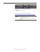
Component Diagrams and Torque Specifications Chapter 1 Torque Specifications The following table lists fastener locations by component, how the fasteners are used, and torque specifications. See Torque Sequence in this chapter for fastening two-point, four-point, and six-point components to the heat sink. Table 1 - Inverter Torque Specifications Torque Component Fastener Application lb•in N•m 24V Power Supply Board Fasten to the Stacking Panel 16 1.
Chapter 1 Component Diagrams and Torque Specifications Torque Component Fastener Application lb•in N•m Side Standoffs and Brackets Fasten Transitional Busbar Assembly to standoffs 50 5.6 Fasten brackets to the drive chassis 26 2.9 Snubber Capacitor Mount Nuts Fasten Snubber Capacitor to the Tie Down Capacitor Mount 26 2.9 Switch Mode Power Supply Board Fasten to the Main Control Panel 16 1.8 Thermal Sensor Fasten to the Main Control Panel 16 1.
Chapter 2 Basic Component Removal Procedures Component removal procedures detailed in this chapter are located on the Inverter and Converter assemblies highlighted below. Components removed in this chapter are to access the Bus Capacitors in the Inverter assembly and the SCR Modules in the Converter assembly. IMPORTANT Photos are for illustration purposes only. Actual components may vary.
Chapter 2 Basic Component Removal Procedures Main Control Panel (Inverter Assembly) See Chapter 1 - Component Diagrams and Torque Specifications to locate components in these instructions. Remove Components 1. Read and follow the Safety Precautions on page 11 and Important Initial Steps on page 12. 2. Remove safety shields and enclosure covers as needed. Mounting Nuts (2) Ribbon Cable from Main Control Board to Power Interface Board (top cable) Ground Wire to TB11 Mounting Screws (2) below TB11 3.
Basic Component Removal Procedures Chapter 2 6. Remove the two mounting screws below TB11. 7. Remove Main Control Panel; support. 8. Disconnect wire harnesses from TB11 to: a. J4 on the Switch Mode Power Supply Board. b. TB1 and TB2 on the Power Interface Board. 9. Label and remove all customer wiring from TB11. 10. Carefully set the Main Control Panel aside. Install Components 1. Reinstall the Main Control Panel Assembly components in the reverse order of removal. 2. Torque panel mounting screws to 2.
Chapter 2 Basic Component Removal Procedures Stacking Panel (Inverter Assembly) See Chapter 1 - Component Diagrams and Torque Specifications to locate components in these instructions. Remove Components 1. Read and follow the Safety Precautions on page 11 and Important Initial Steps on page 12. 2. Remove safety shields and enclosure covers as needed. 3. Remove the Main Control panel. See Main Control Panel (Inverter Assembly) on page 22. 4.
Basic Component Removal Procedures Chapter 2 6. Carefully label and disconnect the red and black wires from TB2 on the DC Bus Filter Board. Do not disconnect the wires from TB1. 7. Disconnect the black Thermal Sensor Wire from J6. Do not remove the sensor from the bracket. 8. Carefully label and disconnect all wiring to TB9. NOTE: TB9 shown with factory wiring only.
Chapter 2 Basic Component Removal Procedures 9. Remove the six nuts for mounting the Stacking Panel. Mounting Nuts (6) 10. Remove Stacking Panel and carefully set aside. Install Components 1. Reinstall the Stacking Panel components in the reverse order of removal. 2. Torque mounting nuts to 5.6 N•m (50 lb•in). 3. Replace all wiring to TB9. 4. Replace the black Thermal Sensor Wire to J6 on the Power Interface Board. 5. Replace the red and black wires from TB2 on the DC Bus Filter Board. 6.
Basic Component Removal Procedures Transitional Busbar Assembly (Inverter Assembly) Chapter 2 See Chapter 1 - Component Diagrams and Torque Specifications to locate components in these instructions. IMPORTANT The instructions detailed in this section describe how to remove the Transitional Busbar assembly as a single unit. Remove Components 1. Read and follow the Safety Precautions on page 11 and Important Initial Steps on page 12. 2. Remove safety shields and enclosure covers as needed. 3.
Chapter 2 Basic Component Removal Procedures 6. If present, remove all customer wiring to Transitional Busbar assembly. 7. Remove the DC Choke output cables. 8. Disconnect the DC+ and DC– cables from the Transitional Busbar assembly. 9. Remove all IGBT Snubber components (3 sets): a. Remove the six Snubber Capacitor mount nuts. Remove capacitors, and save the nuts and capacitors. Tie Down Capacitor Mount Screw Snubber Capacitor Mount Nuts (6) Snubber Capacitors Tie Down Capacitor Mount Screw b.
Basic Component Removal Procedures IMPORTANT Chapter 2 The positive (DC+) Flexible Capacitor Busbars are connected to the back side of the Transitional Busbar assembly. The Transitional Busbar assembly must be removed before the DC+ Flexible Capacitor Busbars can be accessed and removed. 10. Cut tie wraps for the Balancing Resistor wiring. 11. Disconnect the yellow wire for the Balancing Resistor. You do not need to disconnect the blue and black wires. 12.
Chapter 2 Basic Component Removal Procedures IMPORTANT Set screws may come out with the nuts. Save all nuts and set screws. DC Choke Output Cables Upper Capbus Support Nuts (18) attached to Set Screws Note: Photo shows set screws in Capacitors; these set screws may come out with the Transitional Busbar assembly nuts when they are removed. Side Standoffs and Brackets (6) Balancing Resistor Upper and Lower Capbus Support Connecting Brackets Lower Capbus Support Nuts (8) attached to Set Screws 15.
Basic Component Removal Procedures Chapter 2 Install Components See the figures in the preceding Transitional Busbar Assembly (Inverter Assembly) section to identify any components discussed in this section. Negative (DC–) Flexible Capacitor Busbar attached to top side of Transitional Busbar Assembly (3). Positive (DC+) Flexible Capacitor Busbar attached to bottom side of Transitional Busbar Assembly (3).
Chapter 2 Basic Component Removal Procedures 1. Replace the three positive (DC+) Flexible Capacitor Busbars supplied in an IGBT replacement kit on the back side of the Transitional Busbar assembly for each IGBT module being replaced. 2. Mount Transitional Busbar assembly to Bus Capacitors. If needed, use a rubber mallet to gently tap the Transitional Busbar assembly onto the longer set screws of the Bus Capacitors. 3. Add a washer (rounded side down) and nut to each Bus Capacitor set screw.
Basic Component Removal Procedures Chapter 2 16. Reinstall the DC Choke output cables. 17. Reinstall any customer wiring to the Transitional Busbar assembly. 18. Reinstall the Stacking Panel as instructed on page 26. 19. Reinstall the Main Control Panel as instructed on page 23. 20. Verify all wiring to the two panels and the Transitional Busbar assembly has been reconnected. 21. Replace all safety shields and enclosure covers before applying power to the drive.
Chapter 2 Basic Component Removal Procedures Busbar Assembly (Converter Assembly) See Chapter 1 - Component Diagrams and Torque Specifications to locate components in these instructions. Remove Components 1. Read and follow the Safety Precautions on page 11 and Important Initial Steps on page 12. 2. Remove safety shields and enclosure covers as needed. 3. Remove the DC Choke cables from the DC+/DC- Busbars.
Basic Component Removal Procedures Chapter 2 8. Label any AC input cables according to which Bus Flags (R, S, or T) they are connected. Shown with AC Input Cables and Connecting Bolts Removed AC Busbar Mounting Bolt (2 per Busbar) Set Screw Nut for Glastic Standoff (2 per Busbar) AC Bus Flags (1 per Busbar) MOV Wires (black) and Corresponding Snubber Resistor Wires (red). (1 screw per Busbar) 9. Disconnect any AC input cables from the AC Bus Flags and save the connector bolts. 10.
Chapter 2 Basic Component Removal Procedures 14. Carefully label and disconnect all wiring to the three snubber boards on the DC– Busbar. 15. Remove the R phase Snubber Board. Keep the mounting bolt in the S and T phase snubber boards. Mounting Bolts to SCR Modules (3) Precharge Board J1 Red Wire DC1 Terminal Black Wires to DC+ Busbar, (3) Mounting Bolt (3) R S Precharge Board J1 Black Terminal Wire T Snubber Boards Set Screw Nut (2) for Glastic Standoffs 16.
Basic Component Removal Procedures Chapter 2 Install Components 1. Reinstall the Busbars in reverse order of removal. 2. Reinstall the two set screw nuts that secure the DC– Busbar to the glastic standoffs. Torque each set screw to 1.8 N•m (16 lb•in). 3. Reinstall the three bolts, washers, and nuts that secure the DC– Busbar to the SCR Modules. Torque each bolt to 23.5 N•m (208 lb•in). 4. Reinstall the Snubber Resistor terminal wires or connectors to each Snubber Board.
Chapter 2 Basic Component Removal Procedures Notes: 38 Rockwell Automation Publication 20B-IN026B-EN-P - July 2013
Chapter 3 Inverter Assembly Component Replacement Procedures Overview This section details components that are replaceable on the Inverter assembly. See Chapter 4 for components replaceable on the Converter assembly. The components addressed in this section are as follows.
Chapter 3 Inverter Assembly Component Replacement Procedures Main Control Board See Chapter 1 - Component Diagrams and Torque Specifications to locate components in these instructions. Remove Components 1. Read and follow the Safety Precautions on page 11 and Important Initial Steps on page 12. 2. Remove safety shields and enclosure covers as needed.
Inverter Assembly Component Replacement Procedures Chapter 3 8. Loosen the two connector screws for the TB11 Harness Connector on the Main Control Board. Ribbon Cable (J2) to Power Interface Board (J1) Ribbon Cable (J3) to T-Comm Board (J3) Main Control Board Screws (6) Connector Screw TB11 Harness Connector Main Control Board (MCB) Connector Screw 9. Gently pull to disconnect the TB11 Harness Connector from the Main Control Board. Do not disconnect any Harness Connector wires from TB11. 10.
Chapter 3 Inverter Assembly Component Replacement Procedures T-Comm Board See Chapter 1 - Component Diagrams and Torque Specifications to locate components in these instructions. Remove Components 1. Read and follow the Safety Precautions on page 11 and Important Initial Steps on page 12. 2. Remove safety shields and enclosure covers as needed. 3. Remove the HIM Cradle/Board: a. Remove the HIM Module from its slot (if used). b.
Inverter Assembly Component Replacement Procedures Chapter 3 4. Remove the 20-Comm-C Board (if used): a. Disconnect the ribbon cable between the 20-Comm-C Board and T-Comm board; disconnect only from the T-Comm board. b. Remove and save the four mounting screws. 5. If the 20-Comm-C Board is not used, remove the screw securing the T-Comm grounding tab. T-Comm grounding tab screw T-Comm grounding tab flat T-Comm grounding tab upright 6.
Chapter 3 Inverter Assembly Component Replacement Procedures Install Components 1. Install the new T-Comm Board. 2. Verify the board is locked into all seven locking tabs. 3. Carefully bend the T-Comm grounding tab until it is flush with the screw mount on the Main Control Board. 4. Reassemble all components in the reverse order of removal. 5. Tighten the HIM Cradle/Board mounting screws. 6. Reconnect all cables, safety shields, and enclosure covers before applying power to the drive.
Inverter Assembly Component Replacement Procedures Power Interface Board Chapter 3 See Chapter 1 - Component Diagrams and Torque Specifications to locate components in these instructions. Remove Components 1. Read and follow the Safety Precautions on page 11 and Important Initial Steps on page 12. 2. Remove safety shields and enclosure covers as needed. 3. Remove the Main Control Panel. See Main Control Panel (Inverter Assembly) on page 22. 4. Remove wiring to the Power Interface Board. 5.
Chapter 3 Inverter Assembly Component Replacement Procedures Connector Wire Color(s) Connects To: J24 Red/Black TB1 on DC Bus Filter Board TB1 Green/Yellow PE on TB11 TB2 Red #33, #34, and #35 on TB11 6. Remove the two mounting torx screws located on the board as shown at right. 7. Use your fingers or needle-nose pliers to squeeze the tabs of each of the nine spacers (see previous page for their locations), and separate the Power Interface Board from the mounting plate. 8.
Inverter Assembly Component Replacement Procedures Switch Mode Power Supply Board Chapter 3 See Chapter 1 - Component Diagrams and Torque Specifications to locate components in these instructions. Remove Components 1. Read and follow the Safety Precautions on page 11 and Important Initial Steps on page 12. 2. Remove safety shields and enclosure covers as needed. 3. Remove the Main Control Panel. See Main Control Panel (Inverter Assembly) on page 22. 4.
Chapter 3 Inverter Assembly Component Replacement Procedures 6. Use your fingers or needle-nose pliers to squeeze the tabs of each of the three spacers and separate the Switch Mode Power Supply Board from the mounting plate. 7. Remove the Switch Mode Power Supply Board; return or dispose of it properly. Install Components 1. Install the new Switch Mode Power Supply Board. Tighten board screws to 1.8 N•m (16 lb•in). 2. Reconnect all wiring as detailed in the Table on the previous page. 3.
Inverter Assembly Component Replacement Procedures 24V Power Supply Board Chapter 3 See Chapter 1 - Component Diagrams and Torque Specifications to locate components in these instructions. Remove Components 1. Read and follow the Safety Precautions on page 11 and Important Initial Steps on page 12. 2. Remove safety shields and enclosure covers as needed. 3. Remove the safety shield over the 24V Power Supply Board. 4. Carefully label and disconnect all wiring from the 24V Power Supply Board.
Chapter 3 Inverter Assembly Component Replacement Procedures DC Bus Filter Board See Chapter 1 - Component Diagrams and Torque Specifications to locate components in these instructions. Remove Components 1. Read and follow the Safety Precautions on page 11 and Important Initial Steps on page 12. 2. Remove safety shields and enclosure covers as needed. 3. Remove the safety shield over the DC Bus Filter Board. 4. Carefully label and disconnect all wiring from TB1 and TB2 terminals.
Inverter Assembly Component Replacement Procedures Bus Capacitors Chapter 3 See Chapter 1 - Component Diagrams and Torque Specifications to locate components in these instructions. Remove Components 1. Read and follow the Safety Precautions on page 11 and Important Initial Steps on page 12. 2. Remove safety shields and enclosure covers as needed. 3. Remove the Main Control Panel. See Main Control Panel (Inverter Assembly) on page 22. 4. Remove the Stacking Panel.
Chapter 3 Inverter Assembly Component Replacement Procedures 8. The set screws may come out with the nuts. Save all nuts and set screws. 9. Remove the Bus Capacitor Busbar. 10. Remove the Capacitors by pulling them out. ATTENTION: Dispose of the Capacitors properly, in accordance with local regulations and laws. Install Components ATTENTION: Install each capacitor so its vent plug is at the top or 12 o’clock. Component and system damage may result if you position any Bus Capacitor incorrectly. 1.
Inverter Assembly Component Replacement Procedures Capacitor Bank Fan Chapter 3 See Chapter 1 - Component Diagrams and Torque Specifications to locate components in these instructions. Remove Components 1. Read and follow the Safety Precautions on page 11 and Important Initial Steps on page 12. 2. Remove safety shields and enclosure covers as needed. 3. Locate the Capacitor Bank Fan at the bottom of the Capacitor bank. Top Mounting Screw (behind the fan guard screw). 4.
Chapter 3 Inverter Assembly Component Replacement Procedures Inverter Power Module (IGBT) Kit includes: Qty Component 1 IGBT module with circuit board 1 Gate Interface Board 1 Gate Interconnect Harness 3 Flexible Capacitor Busbar, Positive 3 Flexible Capacitor Busbar, Negative 1 Tie Down Capacitor Mount 3 Snubber Capacitor The photograph below is an example of an IGBT module failure.
Inverter Assembly Component Replacement Procedures Chapter 3 Remove Components 1. Read and follow the Safety Precautions on page 11 and Important Initial Steps on page 12. 2. Remove safety shields and enclosure covers as needed. 3. Locate the Inverter Power Module (IGBT Module) to be replaced. 4. If you are replacing the lower IGBT Module, it may be easier if you remove the Main Control Panel and Stacking Panel. If you need to remove the panels, remove them in this order: a.
Chapter 3 Inverter Assembly Component Replacement Procedures 5. Remove the Output Busbar at the Current Transducer: a. Remove and save the torx head bolt that secures the Output Busbar to the AC Output Busbar. b. Remove and save the two hex head bolts that secure the Output Busbar to the U, V, or W Busbar. c. Remove and save the nut and set screw for the Output Busbar standoff. d. Slide the Output Busbar to the right as far as it goes.
Inverter Assembly Component Replacement Procedures Chapter 3 Install Components 1. Carefully examine the Transitional Busbar Assembly and Bus Capacitors for damage. When replacing any IGBT module, we recommend that you replace all Bus Capacitors. If needed, see Bus Capacitors on page 51 to replace damaged Bus Capacitors. 2. Install the IGBT module. a. Use isopropyl alcohol to thoroughly clean the surface of the Heatsink. b. Verify that the mounting surface of the new IGBT module is clean.
Chapter 3 Inverter Assembly Component Replacement Procedures 3. If needed, install the three supplied positive (DC+) Flexible Capacitor Busbars on the back side of the Transitional Busbar Assembly. The positive (DC+) Flexible Capacitor Busbars have a shorter angle. Shown with Transitional Busbar and all Flexible Capacitor Busbars installed for illustration purposes only 2 3 4 5 6 Positive (DC+) Flexible Capacitor Busbars Negative (DC-) Flexible Capacitor Busbars 1 4.
Inverter Assembly Component Replacement Procedures Chapter 3 7. Install the Gate Interface Board: a. Install the Gate Interface Board using the four nuts removed previously. Torque screws to 1.6 N•m (14 lb•in). b. Install the supplied Gate Interconnect Harness. c. Connect wiring between the IGBT and Gate Interface Board as shown in Gate Interface Board on page 60. d. Connect wires to the Current Transducer. 8.
Chapter 3 Inverter Assembly Component Replacement Procedures Gate Interface Board See Chapter 1 - Component Diagrams and Torque Specifications to locate components in these instructions. Remove Components 1. Read and follow the Safety Precautions on page 11 and Important Initial Steps on page 12. 2. Remove safety shields and enclosure covers as needed. 3. Locate the Gate Interface Board to be replaced. 4.
Inverter Assembly Component Replacement Procedures Chapter 3 7. Remove the four mounting nuts. 8. Remove the Gate Interface Board; return or dispose of it properly. Gate Interface Board Mounting Nuts (4; 7 mm) J5 J7 J3 J8 J2 J1 J4 J6 Install Components 1. Install the new board. 2. Torque mounting nuts to 1.8 N•m (16 lb•in). 3. Reconnect wiring as detailed in the Table on the previous page. 4.
Chapter 3 Inverter Assembly Component Replacement Procedures Current Transducer See Chapter 1 - Component Diagrams and Torque Specifications to locate components in these instructions. Remove Components 1. Read and follow the Safety Precautions on page 11 and Important Initial Steps on page 12. 2. Remove safety shields and enclosure covers as needed. 3. Locate the Current Transducer to be replaced. 4. Remove the Output Busbar at the Current Transducer.
Inverter Assembly Component Replacement Procedures Chapter 3 Install Components 1. Mount brackets to the new Current Transducer. Torque screw to 5.6 N•m (50 lb•in). 2. Slide Output Busbar through the Current Transducer assembly with the angled end to the left. 3. Replace the Current Transducer assembly in mounting position by reversing the process used in Step 6. of the removal process. 4. Secure the Current Transducer assembly to the heatsink with two torx screws. Torque to 2.9 N•m (26 lb•in). 5.
Chapter 3 Inverter Assembly Component Replacement Procedures Heatsink Fan See Chapter 1 - Component Diagrams and Torque Specifications to locate components in these instructions. Disconnect TB10 green/ yellow grounding wire. Heatsink Fan Mounting Plate Bolts (16) Heatsink Fan Mounting Bolts (4) Remove Components 1. Read and follow the Safety Precautions on page 11 and Important Initial Steps on page 12. 2. Remove safety shields and enclosure covers as needed. 3.
Inverter Assembly Component Replacement Procedures Thermal Sensor Chapter 3 The Thermal Sensor system for the Inverter Assembly consists of: • A connector to J8 on each of the three Gate Interface Boards. The J8 connectors are wired in series: – J8 (V phase) has four wires: two wires that sense an over-temperature condition, and two wires for temperature feedback. – J8 (U phase) and J8 (W phase) have two wires that sense an over-temperature condition only.
Chapter 3 Inverter Assembly Component Replacement Procedures Install Components 1. For the Main Control Panel thermal sensor, apply a thin layer of supplied thermal grease to the metal side of the new Thermal Sensor and install it with supplied screw with star washer toward the panel. Torque screw to 1.7 N•m (15 lb•in). 2. For the three Gate Interface Boards, carefully route wires and connect to J8 on each Gate Interface Board. Be sure that the J8 connectors go to the correct IGBT.
Inverter Assembly Component Replacement Procedures Balancing Resistor Chapter 3 See Chapter 1 - Component Diagrams and Torque Specifications to locate components in these instructions. Remove Components 1. Read and follow the Safety Precautions on page 11 and Important Initial Steps on page 12. 2. Remove safety shields and enclosure covers as needed. 3. Locate the Balancing Resistor to be replaced. Balancing Resistor 4. Label and disconnect all wires for the Balancing Resistor. 5.
Chapter 3 Inverter Assembly Component Replacement Procedures 5. Reconnect all wires for the Balancing Resistor. Wire Color Yellow Black Blue To Capacitor Busbar (lower 8-bank) Negative (–) CNVT (+) 6. Replace all safety shields and enclosure covers before applying power to the drive.
Inverter Assembly Component Replacement Procedures Fan Transformer (IP20 version only) Chapter 3 See Chapter 1 - Component Diagrams and Torque Specifications to locate components in these instructions. Remove Components 1. Read and follow the Safety Precautions on page 11 and Important Initial Steps on page 12. 2. Remove safety shields and enclosure covers as needed. Label and disconnect any wires connected here. Fan Transformer Mounting bracket screws (4) 3.
Chapter 3 Inverter Assembly Component Replacement Procedures Notes: 70 Rockwell Automation Publication 20B-IN026B-EN-P - July 2013
Chapter 4 Converter Assembly Component Replacement Procedures Overview This section details components that are replaceable on the converter assembly. See Chapter 3 for components replaceable on the inverter assembly. The components addressed in this section are as follows.
Chapter 4 Converter Assembly Component Replacement Procedures DC Link Choke See Chapter 1 - Component Diagrams and Torque Specifications to locate components in these instructions. Note: For the IP20 model, the DC Link Choke is mounted at the bottom front of the enclosure. For the IP00 model, the DC Link Choke is supplied loose and is mounted per installation environment (typically in a similar location as IP20). Remove Components 1.
Converter Assembly Component Replacement Procedures MOV Surge Suppressor Chapter 4 See Chapter 1 - Component Diagrams and Torque Specifications to locate components in these instructions. Remove Components 1. Read and follow the Safety Precautions on page 11 and Important Initial Steps on page 12. 2. Remove safety shields and enclosure covers as needed. 3. Locate the MOV Surge Suppressor assembly. 4. Remove the MOV enclosure cover (2 nuts).
Chapter 4 Converter Assembly Component Replacement Procedures Converter Power Modules (SCR) IMPORTANT If any Converter SCR module fails, all three phases should be replaced (one kit includes two Converter SCR modules for one phase). See Chapter 1 - Component Diagrams and Torque Specifications to locate components in these instructions. Remove Components 1. Read and follow the Safety Precautions on page 11 and Important Initial Steps on page 12. 2. Remove safety shields and enclosure covers as needed.
Converter Assembly Component Replacement Procedures Chapter 4 Install Components 1. Use isopropyl alcohol to thoroughly clean the Heatsink mounting surface where the SCR modules will be installed. 2. Verify the mounting surface of the new SCR module is clean. If not, clean with isopropyl alcohol. 3. Use a 3- or 4-inch paint roller or putty knife to apply a thin, even coating of the supplied thermal grease to the mounting surface of each SCR module.
Chapter 4 Converter Assembly Component Replacement Procedures 6. Reinstall the Precharge Board wires to the MOV modules. SCR Modules (6) Installed with Wiring Plug Facing the top of the chassis. Red and White Wires from Upper SCR Modules to J2 on the Precharge Board Red and White Wires from Lower SCR Modules to J3 on the Precharge Board J3 and J2 on the Precharge Board 7. Reinstall the busbars and all Busbar wires. See Install Components on page 37. 8. Reinstall the DC cables.
Converter Assembly Component Replacement Procedures Precharge Board Chapter 4 See Chapter 1 - Component Diagrams and Torque Specifications to locate components in these instructions. Remove Components 1. Read and follow the Safety Precautions on page 11 and Important Initial Steps on page 12. 2. Remove safety shields and enclosure covers as needed. 3. Carefully label and disconnect all wiring plugs from the Precharge Board. J1 J3 Mounting Screw (1) J2 Spacers (3) 4.
Chapter 4 Converter Assembly Component Replacement Procedures Install Components 1. Install the new Precharge Board. 2. Torque the Precharge Board mounting screw to 1.8 N•m (16 lb•in). 3. Reconnect all wiring plugs as shown in the figure on the previous page. 4. Replace all safety shields and enclosure covers before applying power to the drive.
Converter Assembly Component Replacement Procedures Snubber Resistors Chapter 4 See Chapter 1 - Component Diagrams and Torque Specifications to locate components in these instructions. Remove Components 1. Read and follow the Safety Precautions on page 11 and Important Initial Steps on page 12. 2. Remove safety shields and enclosure covers as needed. 3. Locate the Snubber Resistor(s) to be replaced.
Chapter 4 Converter Assembly Component Replacement Procedures Install Components 1. Use isopropyl alcohol to clean the surface where the new Snubber Resistor(s) will be installed. 2. Verify that the mounting surface of the new Snubber Resistor(s) is clean. If not, clean with isopropyl alcohol. 3. Use a 3-inch paint roller or putty knife to apply a thin even coating of the supplied thermal grease to the mounting surface of the new Snubber Resistor(s) and install. 4. Install the new Snubber Resistor(s).
Converter Assembly Component Replacement Procedures Snubber Boards Chapter 4 See Chapter 1 - Component Diagrams and Torque Specifications to locate the component detailed in these instructions. Remove Components 1. Read and follow the Safety Precautions on page 11 and Important Initial Steps on page 12. 2. Remove safety shields and enclosure covers as needed. 3. Locate the Snubber Board(s) to be replaced. DC1 Terminal Screw Mounting Screw R S T 4.
Chapter 4 Converter Assembly Component Replacement Procedures Install Components 1. Torque the DC1 terminal screw and mounting screw to 2.9 N•m (26 lb•in). 2. Reinstall the terminal wires or connectors to each Snubber Board.
Converter Assembly Component Replacement Procedures Thermal Sensor Chapter 4 The Thermal Sensor system for the Converter Assembly consists of two sensors. Both sensors have a tripping point of 105 °C (221 °F). • Sensor TSW1 is located on the upper heatsink • Sensor TSW2 is located on the lower heatsink TSW1 Thermal Sensor The thermal sensors are wired in tandem and are connected to the J6 connector on the Power Interface Board on the Inverter.
Chapter 4 Converter Assembly Component Replacement Procedures Install Components 1. Use isopropyl alcohol to clean the surface where the new Thermal Sensor will be installed. 2. Apply a thin layer of supplied thermal grease to the metal side of the new Thermal Sensor and install it with supplied screw with star washer. 3. Torque screw to 0.6 N•m (6 lb•in). 4. Reconnect the wiring harness to the J6 connector on the Power Interface Board on the Inverter. See page 45 for connector locations. 5.
Converter Assembly Component Replacement Procedures Heatsink Fan Assembly Chapter 4 See Chapter 1 - Component Diagrams and Torque Specifications to locate components in these instructions. Heatsink Fan Mounting Plate Bolts (12) Heatsink Fan Mounting Bolts (4) TB12 and Fan Capacitor Wiring Plugs Remove Components 1. Read and follow the Safety Precautions on page 11 and Important Initial Steps on page 12. 2. Remove safety shields and enclosure covers as needed. 3.
Chapter 4 Converter Assembly Component Replacement Procedures Install Components 1. Install the new heatsink fan to the mounting plate. Torque the mounting screws to 5.6 N•m (50 lb•in). 2. Install the new gasket (if needed) and mounting plate to the chassis. Torque the mounting screws to 2.9 N•m (26 lb•in). 3. Connect the wires from TB12 to the Transformer (120, N, PE). 4. Connect the wiring plugs, and reinstall the plastic wire ties. 5.
Rockwell Automation Support Rockwell Automation provides technical information on the Web to assist you in using its products. At http://www.rockwellautomation.com/support you can find technical and application notes, sample code, and links to software service packs. You can also visit our Support Center at https://rockwellautomation.custhelp.com/ for software updates, support chats and forums, technical information, FAQs, and to sign up for product notification updates.