Installation Instructions PowerFlex 700 Drive - Frame 7 Components Replacement
Important User Information Solid-state equipment has operational characteristics differing from those of electromechanical equipment. Safety Guidelines for the Application, Installation and Maintenance of Solid State Controls (publication SGI-1.1 available from your local Rockwell Automation sales office or online at http://www.rockwellautomation.com/literature/) describes some important differences between solid-state equipment and hard-wired electromechanical devices.
Table of Contents Important User Information . . . . . . . . . . . . . . . . . . . . . . . . . . . . . . . . . . . . . . . 2 Summary of Changes New and Updated Information. . . . . . . . . . . . . . . . . . . . . . . . . . . . . . . . . . . . . 5 Preface Introduction . . . . . . . . . . . . . . . . . . . . . . . . . . . . . . . . . . . . . . . . . . . . . . . . . . . . . . 7 Component Kits . . . . . . . . . . . . . . . . . . . . . . . . . . . . . . . . . . . . . . . . . . . . . . . . . .
Table of Contents Notes: 4 Rockwell Automation Publication 20B-IN017B-EN-P - September 2011
Summary of Changes This manual contains new and updated information. New and Updated Information This table contains the changes made to this revision. Topic Page Added Heatsink Fan Transformer kit, 1336-T-SP5A, to table of component kits. (Instructions were already in this manual, but the kit was not listed in the table.) 7 Added T-Comm Board kit, SK-G9-TCOMM, to table of component kits. 7 Added T-Comm Board removal and installation instructions.
Summary of Changes Notes: 6 Rockwell Automation Publication 20B-IN017B-EN-P - September 2011
Preface Introduction This publication provides guidelines for replacing the major components in the PowerFlex 700 Frame 7 drive. Component Kits All kits include necessary components, ESD wrist strap and hardware (if required), and thermal grease (if required). Description Precharge Board Heatsink Fan Heatsink Fan Transformer Current Transducer Inverter Power Module (IGBT) Kit Catalog No.
Preface Recommended Tools The following list of tools is provided for your reference to disassemble and assemble the drive and components. This list may not be all-encompassing for your situation. Not all tools are needed for some components. Refer to pertinent sections for details.
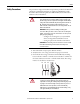
Preface Safety Precautions The precautions and general installation requirements provided in the PowerFlex 700 Frame 7-10 Installation Instructions (publication 20B-IN014) and the PowerFlex 700 User Manual (publication 20B-UM002) must be followed in addition to those included here. ATTENTION: To avoid an electric shock hazard, ensure that all power has been removed before proceeding. In addition, before servicing, verify that the voltage on the bus capacitors has discharged.
Preface ATTENTION: The information in this publication is merely a guide for proper installation. Rockwell Automation, Inc. cannot assume responsibility for the compliance or the noncompliance to any code (national, local, or otherwise) for the proper installation of this drive or associated equipment. A hazard of personal injury and/or equipment damage exists if codes are ignored.
Preface Important Initial Steps Read and follow these statements before performing any service on the drive. · Read and follow the precautions in Safety Precautions on page 9. · Identify components to be replaced using the figures in Component Diagrams and Torque Specs on page 13. · Remove protective shields only as necessary. · Before disconnecting any wire or cable, verify that it is labeled. Also, when removing components, note hardware type and location.
Preface Notes: 12 Rockwell Automation Publication 20B-IN017B-EN-P - September 2011
Chapter 1 Component Diagrams and Torque Specs AC input drive is shown.
Chapter 1 Component Diagrams and Torque Specs AC input drive is shown.
Component Diagrams and Torque Specs Chapter 1 Inverter Section Current Transducers Current Transducer Mounting Clamps Inverter Snubber Boards Motor Bus Bars Gate Interface Boards Inverter Power Module IGBTs Bottom of Drive Top of Drive Current Transducers (behind Mounting Clamps) Motor Bus Bars Inverter Snubber Boards IGBT Bus Bars Gate Interface Boards Inverter Power Module IGBTs Note: Components are shown as seen from right side without drive covers.
Chapter 1 Component Diagrams and Torque Specs Main Control Panel Assembly Bottom of Drive Top of Drive Components are listed left to right for each level Front HIM Communications Panel TB11 and Main Control Board Main Control Panel Switch Mode Power Supply Board and Power Interface Board Stacking Panel Back Note: Components are shown as seen from right side without drive covers.
Component Diagrams and Torque Specs Chapter 1 Figure 2 - Four-Point Mounting 1 3 4 2 2 1 3 4 2 1 Initial Sequence 4 3 Final Sequence Figure 3 - Six-Point Mounting 1 2 6 2 4 3 1 5 3 4 5 6 Initial Sequence Do not exceed 0.7 Newton-meters (6 lb•in) on initial torque of all six screws.
Chapter 1 Component Diagrams and Torque Specs Torque Specifications The following table lists fastener locations by component, how the fasteners are used, and torque specifications. Refer to Torque Sequence in this chapter for fastening two-point, four-point, and six-point components to the heat sink.
Component Diagrams and Torque Specs Chapter 1 Component Fastener Application Torque lb•in Torque N•m Wires Wires to TB2 7 0.8 Wires Wires to TB3 8 – 10 0.9 – 1.
Chapter 1 Component Diagrams and Torque Specs Notes: 20 Rockwell Automation Publication 20B-IN017B-EN-P - September 2011
Chapter 2 Basic Component Removal Procedures The procedures in this section are required by many of the replacement procedures described in this manual in addition to replacement of these components themselves. DO NOT perform any of the procedures in this section unless specified by the instructions for the component you are replacing. Remove Main Control Panel Assembly Refer to the figures in Component Diagrams and Torque Specs on page 13 for these instructions. Remove Components 1.
Chapter 2 Basic Component Removal Procedures 6. Remove the two nuts at the top of the Main Control Panel. ! CAUTION HOT SURFACES 7. Remove Main Control Panel; support. 8. Disconnect wire harnesses from TB11 to the Switch Mode Power Supply Board ( J4 connector) and at TB1 and TB2 on the Power Interface Board. 9. Label and disconnect all customer wiring from TB11. 10. Carefully set the Main Control Panel aside.
Basic Component Removal Procedures Chapter 2 Install Components When instructed for the component you are replacing, reinstall the Stacking Panel components in the reverse order of removal. Refer to the figures in Component Diagrams and Torque Specs on page 13 for these instructions. Remove Precharge Board Assembly Remove Components 1. Read and follow the Safety Precautions on page 9 and Important Initial Steps on page 11. 2.
Chapter 2 Basic Component Removal Procedures Remove these screws Figure 4 - Screws on Panel over Transitional Bus Bar TIP When you remove the screws in the next step, you will remove the Bus Fuse as well. There is a plate over the top end of the Bus Fuse which will be free upon removal of the screws. Do not let the plate fall. 4. Using Figure 4 -, remove the seventeen (17) screws for the Transitional Bus Bar. 5. Slide the Transitional Bus Bar to the left and out.
Chapter 3 Component Replacement Procedures Precharge Board Refer to the figures in Component Diagrams and Torque Specs on page 13 for these instructions. Remove Components 1. Read and follow the Safety Precautions on page 9 and Important Initial Steps on page 11. 2. Remove the safety cover over the Precharge Board. 3. For DC input only: Verify that customer wiring to TB2 is properly labeled and then disconnect wiring from TB2. 4.
Chapter 3 Component Replacement Procedures Main Control Board Refer to the figures in Component Diagrams and Torque Specs on page 13 for these instructions. Remove Components 1. Read and follow the Safety Precautions on page 9 and Important Initial Steps on page 11. 2. Remove safety shields as needed.
Component Replacement Procedures Chapter 3 Install Components 1. Install the new Main Control Board. 2. Reassemble all components in the reverse order of removal. 3. Reconnect all cables. 4. Replace all safety shields and enclosure covers before applying power to the drive. T-Comm Board See Component Diagrams and Torque Specs on page 13 to locate the component detailed in these instructions. Remove Components 1. Read and follow the Safety Precautions on page 9 and Important Initial Steps on page 11. 2.
Chapter 3 Component Replacement Procedures f. Remove the Main Control Board. HIM Board slot Ribbon Cable Connector Mounting Screw Ribbon Cable Connection to T-Comm Board Wiring Connector Grounding-Wire Screw Optional 20-Comm-x Board Detail Mounting Screws (4) Mounting Screw 3. Remove the 20-Comm-x Board (if used): a. Disconnect the ribbon cable between the 20-Comm-x Board and T-Comm board; disconnect only from the T-Comm board. b. Remove and save the four mounting screws. 4.
Component Replacement Procedures Chapter 3 6. If needed, use the same flathead screwdriver tip to pry the seven locking tabs away from the T-Comm Board. T-Comm Board Locking Tab Locations Five locking tabs are on the back side of the Main Control Board (above); two are on the front side in the area between the optional HIM and 20-Comm-x board slots (upper right). NOTE: Use a flathead screwdriver tip to pry the locking tabs away from the T-Comm Board (lower right). 7.
Chapter 3 Component Replacement Procedures Switch Mode Power Supply Board Refer to the figures in Component Diagrams and Torque Specs on page 13 for these instructions. Remove Components 1. Perform Remove Main Control Panel Assembly on page 21. 2. Disconnect all cables ( J2, J4, J3, J1) from the Switch Mode Power Supply Board. 3. Remove the Switch Mode Power Supply Board mounting star screw located at the lower right corner of the board. Spacers 4.
Component Replacement Procedures Power Interface Board Chapter 3 Refer to the figures in Component Diagrams and Torque Specs on page 13 for these instructions. Remove Components 1. Read and follow the Safety Precautions on page 9 and Important Initial Steps on page 11. 2. Perform Remove Main Control Panel Assembly on page 21. 3. Remove remaining wiring harnesses from the Power Interface Board, including the wiring between the Power Interface Board and the Switch Mode Power Supply Board.
Chapter 3 Component Replacement Procedures Install Components 1. Install the new Power Interface Board. Tighten board screws to 1.7 N•m (15 lb•in) 2. Reconnect all wiring except the ribbon cable going from the Power Interface Board ( J1) to the Main Control Board ( J2). 3. Reinstall the Main Control Panel Assembly. Tighten sheet metal screws to 3.2 N•m (28 lb•in) 4. Reconnect the ribbon cable going from the Power Interface Board ( J1) to the Main Control Board ( J2). 5.
Component Replacement Procedures Chapter 3 Remove Components 1. Read and follow the Safety Precautions on page 9 and Important Initial Steps on page 11. 2. Perform Remove Main Control Panel Assembly on page 21. 3. Perform Remove Stacking Panel on page 22. 4. Perform Remove Precharge Board Assembly on page 23. 5.
Chapter 3 Component Replacement Procedures 8. Remove the screws and accompanying wires for R, S, and T Bus Bars at the SCR. 9. Remove the R, S, T Bus Bars. TIP Label Bus Bars for correct orientation when reinstalling later. 10. Remove at least two terminal blocks from the R, S, T Bus Bars at SCR DIN rail by pushing down on the metal tab on top of the terminal block while lifting the bottom of the terminal block out toward you and up.
Component Replacement Procedures Chapter 3 3. Install the four screws that hold the Fan and cover together. 4. Place Fan unit in position, locating Fan wire in bottom left corner. 5. Install the 12 screws at the exterior of fan cover. 6. Reconnect Fan wire. 7. Reassemble remaining components in reverse order. TIP When replacing Motor Bus Bars, remove nearby terminal block barriers to provide additional maneuvering space. 8.
Chapter 3 Component Replacement Procedures 3. Locate the Current Transducer to be replaced. W Phase V Phase U Phase 4. Disconnect the wiring harness from the transducer board. Clip the wire tie and remove the wiring harness. 5. Remove the three button head screws that secure the bus bar. Move the bus bar and transducer to an ESDsafe flat surface for working with it. 6.
Component Replacement Procedures Chapter 3 9. Remove transducer assembly (transducer and board) from the bus bar by sliding the gentle bend of the bus bar (the end with only one screw hole) through the assembly, taking care not to damage the insulation on the bus bar or loosen the wiring. Discard old transducer. Install Components 1. Position the mounting bar with the end with two screw holes to your right. 2.
Chapter 3 Component Replacement Procedures 7. Loosen the mounting bracket screws and align the CT assembly on the bus bar with the remaining transducers. 8. Torque the mounting bracket screws to 5.9 N•m (52 lb•in) 9. Reconnect the wiring harness. Secure with a wire tie. 10. Replace all safety shields and enclosure covers before applying power to the drive. Inverter Snubber Board Important: The Inverter Snubber Board and its associated Resistor do not need to be replaced at the same time.
Component Replacement Procedures Chapter 3 7. For all Snubber Boards, remove the U-Phase Motor Bus Bar to gain access to the board being replaced. TIP Depending on spacing, it may be required that all three CTs and Bus Bars be removed before the U Phase Bus Bar can be removed. a. Remove the top nut at the U-Phase output terminal block. b. If not already removed, disconnect the U-Phase Current Transducer at its top end. c. Slide the Motor Bus Bar out of the notch at the top. d.
Chapter 3 Component Replacement Procedures Inverter Snubber Resistor Important: The Inverter Snubber Board and its associated Resistor do not need to be replaced at the same time. Test the Resistor as instructed below before replacing it. Refer to the figures in Component Diagrams and Torque Specs on page 13 for these instructions. Remove Components 1. Read and follow the Safety Precautions on page 9 and Important Initial Steps on page 11. 2. Remove safety shields as needed. 3.
Component Replacement Procedures Chapter 3 4. Perform Remove Main Control Panel Assembly on page 21. 5. Perform Remove Stacking Panel on page 22. 6. Perform Remove Transitional Bus Bar on page 23. 7. Using pliers, remove the wire with push-on connector from the Snubber Board associated with the Resistor to be replaced. To locate its Resistor, follow the wire from the Snubber Board to its Resistor, carefully clipping the wire ties along the way. 8.
Chapter 3 Component Replacement Procedures Inverter Power Module (IGBT) Important: Kit includes two (2) IGBT modules and two (2) Gate Interface Boards. It is recommended that both IGBT modules for a phase be replaced at the same time. Refer to the figures in Component Diagrams and Torque Specs on page 13 for these instructions. Remove Components 1. Read and follow the Safety Precautions on page 9 and Important Initial Steps on page 11. 2. Locate the Inverter Power Module to be replaced. 3.
Component Replacement Procedures Chapter 3 10. Remove the Gate Interface Boards (three (3) screws) and discard. 11. Remove the six (6) screws for the IGBT modules. 12. Remove the IGBT modules by tipping the top edge out first. Discard. Note: Picture shows new IGBT modules with conductive tape, but existing modules will not have conductive tape. Install Components 1. Perform the following steps for one IGBT module at a time. a. Using isopropyl alcohol, thoroughly clean the surface of the Heatsink.
Chapter 3 Component Replacement Procedures e. Remove the conductive tape from the IGBT module and immediately install a new Gate Interface Board. After the conductive tape is removed, the IGBT module’s gate terminals must not be exposed longer than one minute. 2. Repeat Step 1. for the second IGBT module. 3. Reconnect the Gate Interface Board connections. 4. Place the IGBT Bus Bar on the IGBT modules (over the Gate Interface Boards) with its flanges fitting over and under the Transitional Bus Bar.
Component Replacement Procedures Chapter 3 13. Torque the left screws for each Current Transducer to 5.9 N•m (52 lb•in) 14. Set each Motor Bus Bar in final position and torque the remaining Current Transducer screw to 5.9 N•m (52 lb•in) 15. Torque each Motor Bus Bar mounting screw (at the bottom) to 9.0 N•m (80 lb•in) 16. Reassemble remaining components in reverse order. 17. Replace all safety shields and enclosure covers before applying power to the drive.
Chapter 3 Component Replacement Procedures Heatsink Thermal Sensor The Heatsink Thermal Sensor is located at the top of the Heatsink under the U Phase Gate Interface Board, with beige insulated wiring. It is connected to the Power Interface Board assembly by the Monitor Wire. Heatsink Thermal Sensor Refer to the diagram above and to the figures in Component Diagrams and Torque Specs on page 13 for these instructions. Remove Components 1.
Component Replacement Procedures Chapter 3 12. Remove the left Gate Interface Board located over the Heatsink Thermal Sensor. You do not need to disconnect the connector. 13. Connect the jumper wire to gate connections on the IGBT module. ➍ Jumper here ➎ IGBT Torque Seque ➋ ➊ ➏ ➌ First Sequence: 0.7 N-m Final Sequence: 3.6 N-m 14. Carefully cut the wire ties securing the Heatsink Thermal Sensor. Do Not cut the harness. 15.
Component Replacement Procedures Bus Fuse The Bus Fuse is located on the Transitional Bus Bar. Refer to the figure here and the figures in Component Diagrams and Torque Specs on page 13 for these instructions. Remove Components Bus Fuse Screws Chapter 3 1. Read and follow the Safety Precautions on page 9 and Important Initial Steps on page 11. TIP Bus Fuse Bus Fuse Ground Cable When you remove the screws in the next step, you will remove the Bus Fuse as well.
Component Replacement Procedures Bus Capacitor Chapter 3 Refer to the figures in Component Diagrams and Torque Specs on page 13 for these instructions. Remove Components 1. Read and follow the Safety Precautions on page 9 and Important Initial Steps on page 11. 2. Perform Remove Transitional Bus Bar on page 23. 3. Label and remove all wires and connectors from the Bus Capacitor Bus Bar. 4. Remove nuts and washers fastening the Bus Capacitor Bus Bar. 5. Remove the Bus Capacitor Bus Bar. 6.
Chapter 3 Component Replacement Procedures Converter Snubber Board - AC Input Only Refer to the figures in Component Diagrams and Torque Specs on page 13 for these instructions. Remove Components 1. Read and follow the Safety Precautions on page 9 and Important Initial Steps on page 11. 2. Locate the Converter Snubber Board to be replaced. (Some wires below shown disconnected.) T R S 3. Perform Remove Main Control Panel Assembly on page 21. 4. Perform Remove Stacking Panel on page 22. 5.
Component Replacement Procedures Converter Power Module (SCR) - AC Input Only Chapter 3 Important: If any SCR module fails, all three SCR modules should be replaced. (Kit includes all three modules.) Refer to the figures in Component Diagrams and Torque Specs on page 13 for these instructions. Remove Components 1. Read and follow the Safety Precautions on page 9 and Important Initial Steps on page 11. 2. Locate the Converter SCR modules (R, S, T) to be replaced. Converter SCR Modules 3.
Chapter 3 Component Replacement Procedures 12. Remove the Converter Bus Bars (DC+ and DC–). DC– DC+ DC Choke Connectors Snubber Board Mounting Bracket Converter Bus Bars SCR module 13. Disconnect the SCR gate leads. 14. Remove the four (4) Phillips screws that hold each SCR to the Heatsink. 15. Remove the SCR modules. Install Components 1. Using isopropyl alcohol, thoroughly clean the surface of the Heatsink. 2. Verify that the mounting surface of each new SCR module is clean.
Component Replacement Procedures Chapter 3 5. Install the SCR module leads from the Precharge Board J2 and J3. For each SCR module, the left connection is for the J3 lead and the right connection is for the J2 lead. Note: J3 has its red wire on the left and white wire on the right, while J2 has its red wire on the right and white wire on the left. J3 Lead Connection J2 Lead Connection 6. Install the Converter Bus Bars (DC+ and DC–) per the diagram in Step 12.
Chapter 3 Component Replacement Procedures MOV - AC Input Only Refer to the figures in Component Diagrams and Torque Specs on page 13 for these instructions. Remove Components 1. Read and follow the Safety Precautions on page 9 and Important Initial Steps on page 11. 2. Locate the MOV assembly. 3. Perform Remove Precharge Board Assembly on page 23. 4. Note wire placement and connections. Disconnect the MOV ground wire and its R, S, and T wires at the top nut on the input power terminal block. 5.
Component Replacement Procedures DC Link Choke - AC Input Only Chapter 3 Refer to the figures in Component Diagrams and Torque Specs on page 13 for these instructions. Remove Components 1. Read and follow the Safety Precautions on page 9 and Important Initial Steps on page 11. 2. Locate the DC Link Choke. 3. Perform Remove Main Control Panel Assembly on page 21. 4. Perform Remove Stacking Panel on page 22. 5.
Chapter 3 Component Replacement Procedures Precharge SCR Module Snubber Board - DC Input Only Figure 5 - Precharge SCR Module Location (DC Input Drive Shown) Precharge SCR Module and Snubber Refer to the figures in Component Diagrams and Torque Specs on page 13 and Figure 5 - above for these instructions. Remove Components 1. Read and follow the Safety Precautions on page 9 and Important Initial Steps on page 11. 2. Locate the Precharge SCR module Snubber Board to be replaced. 3.
Component Replacement Procedures Chapter 3 Install Components 1. Replace washers on Snubber Board Bus Bar studs. 2. Replace insulation over washers. 3. Place new Snubber Board over insulation. 4. Install M6 nuts on studs with star washer side facing Snubber Board. Do not tighten yet. 5. Center insulation around washers so it is not pinched between the Bus Bar and any washer or nut. 6. Torque M6 nuts to 2.9 N•m (26 lb•in) 7. Replace push-on wire. 8. Reassemble remaining components in reverse order. 9.
Chapter 3 Component Replacement Procedures Install Components 1. Clean the surface of the Heatsink mounting surface with isopropyl alcohol. 2. Thoroughly clean the mounting surface of the new SCR module and apply a thin even coating of the supplied thermal grease. 3. Install SCR module with supplied screws and torque using the sequence and specifications shown in the diagram below. ➊ ➌ SCR Torque SCR Torque First Sequence: 0.7 N-m (6.0 lb.-in.) Final Sequence: 5.6 N-m (50 lb.-in.
Rockwell Automation Support Rockwell Automation provides technical information on the Web to assist you in using its products. At http://www.rockwellautomation.com/support/, you can find technical manuals, a knowledge base of FAQs, technical and application notes, sample code and links to software service packs, and a MySupport feature that you can customize to make the best use of these tools.