
Manual


Rockwell Automation Publication 20B-IN024C-EN-P - June 2012 73
Component Replacement Procedures Chapter 3
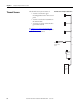
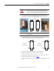
• The SCR (on the left) has a plug with prongs located at the bottom.
• The diode (on the right) has a plug without prongs located at the top.
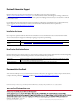
3. Install the SCR module or diode with supplied screws and torque using the
sequences and specifications shown in the diagram below.
4. Install the precharge busbars. Torque to 5.6 N•m (50 lb•in).
5. Install the precharge wires. Torque to 2.9 N•m (26 lb•in).
6. Install the precharge cables. Torque the screws to 12.2 N•m (108 lb•in).
7. Install the stacking panel as detailed on page 27
.
8. Replace all safety shields and enclosure covers before applying power to the
drive.
WARNING: In the next step, be sure to properly install the
modules as shown. If you install the SCR incorrectly, it will not
work. If you install the diode incorrectly, then the drive and the bus
capacitors may not operate properly and may prematurely fail.
IMPORTANT
In the next step, take care to not disturb any of the thermal grease on
the SCR module.
SCR
Diode
Plug
with Prongs
Plug with
No Prongs
➊➌
➍➋
➌
➍➋
➊
First Torque
Sequence:
0.7 N•m (6.0 lb•in)
Final Torque
Sequence:
5.6 N•m (50 lb•in)