
Manual


Rockwell Automation Publication 20B-IN024C-EN-P - June 2012 71
Component Replacement Procedures Chapter 3
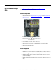
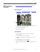
MOV Surge Suppressor -
AC Input Only
See Chapter 1 - Component Diagrams and Torque Specifications to locate the
component
detailed in these instructions.
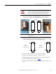
Remove Components
1. Read and follow the Safety Precautions on page 12 and Important Initial
Steps on page 13.
2. Remove the stacking panel as detailed on page 26
.
3. Note wire placement and connections. Disconnect the MOV ground wire
and the R, S, and T wires to the AC busbars.
4. Remove the MOV mounting nut.
5. Remove the MOV assembly.
Install Components
1. Install the new MOV assembly. Torque the MOV mounting nut to
2.9 N•m (26 lb•in).
2. Connect all wires and connectors for the MOV.
3. Torque the R, S, and T Phase power terminal block screws to 2.9 N•m
(26 lb•in).
4. Torque the ground wire nut to 9.0 N•m (80 lb•in).
5. Install the stacking panel as detailed on page 27
.
6. Replace all safety shields and enclosure covers before applying power to the
drive.
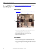
MOV