
Manual

Rockwell Automation Publication 20B-IN024C-EN-P - June 2012 59
Component Replacement Procedures Chapter 3
Install Components
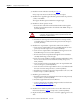
1. Use isopropyl alcohol to thoroughly clean the mounting surface of the
heatsink and the mounting surface of the new snubber resistor.
2. Use a 3-inch paint roller or putty knife to apply a thin even coating of the
supplied thermal grease to the mounting surface of the new snubber
resistor and install. Torque screws to 2.9 N•m (26 lb•in).
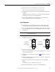
3. Connect the wires.
4. For the R snubber resistor only: Install the transitional busbar assembly
as detailed on page 32
.
5. Install stacking panel as detailed on page 27
.
6. Replace all safety shields and enclosure covers before applying power to the
drive.
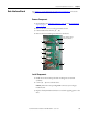
Converter Snubber Board -
AC Input Only
See Chapter 1 - Component Diagrams and Torque Specifications to locate the
component
detailed in these instructions.
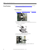
Remove Components
1. Read and follow the Safety Precautions on page 12 and Important Initial
Steps on page 13.
2. Remove the stacking panel as detailed on page 26
.
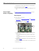
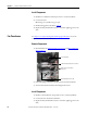
3. Label and disconnect wires from the converter snubber board to be
replaced.
4. Remove the two screws that secure the board.
5. Remove the board.
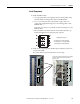
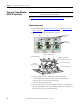
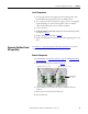
Snubber Board for “R” SCR
Snubber Board for “S” SCR
Snubber Board
for “T” SCR