
Manual

58 Rockwell Automation Publication 20B-IN024C-EN-P - June 2012
Chapter 3 Component Replacement Procedures
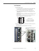
9. Reinstall the DC+ and DC- busbars and torque to 9.0 N•m (80 lb•in).
10. Install stacking panel as detailed on page 27
.
11. Replace all safety shields and enclosure covers before applying power to the
drive.
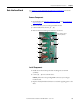
Converter Snubber
Resistors - AC Input Only
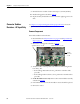
See Chapter 1 - Component Diagrams and Torque Specifications to locate the
component
detailed in these instructions.
Remove Components
Kit includes snubber board and resistor.
1. Read and follow the Safety Precautions on page 12
and Important Initial
Steps on page 13.
2. Remove the stacking panel as detailed on page 26
.
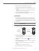
3. Verify the snubber resistor(s) with a volt ohm meter. The reading should
be 8 ohms ± 10%.
• If the reading is not within tolerance, perform the remainder of this
procedure.
• If the reading is within tolerance, do not perform the remainder of this
procedure.
4. For the R snubber resistor only: Remove the transitional busbar assembly
as detailed on page 28
.
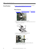
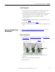
5. Label and disconnect the wires from snubber resistors that will be replaced.
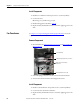
6. Remove the resistor.
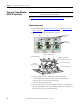
Snubber Resistor for “R” SCR
Snubber Resistor for “S” SCR
Snubber
Resistor for
“T” SCR