
Manual

Rockwell Automation Publication 20B-IN024C-EN-P - June 2012 55
Component Replacement Procedures Chapter 3
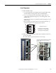
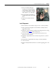
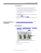
7. Remove assembly by lifting the
assembly up and turning it slightly
counterclockwise while rotating the
top of the output busbar toward you
and around the U, V, or W busbar.
8. Move the busbar and transducer to
an ESD-safe flat surface for working
with it.
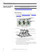
9. Separate the transducer from the
brackets.
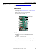
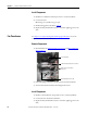
Install Components
1. Mount brackets to the transducer. Torque screws to 1.6 N•m (14 lb•in).
2. Slide output busbar through the current transducer assembly with the
angled end to the left.
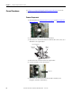
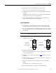
3. Replace the current transducer assembly in mounting position by reversing
the process used in Step 7.
of the removal process.
4. Secure the transducer assembly to the drive chassis with two screws.
Torque to 2.9 N•m (26 lb•in).
5. Replace the output busbar setscrew and nut. Torque the nut to 5.6 N•m
(50 lb•in).
6. Install the three output busbar bolts. Torque to 9.0 N•m (80 lb•in).
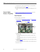
7. Connect the wires.
8. Replace all safety shields and enclosure covers before applying power to the
drive.