
Manual

Rockwell Automation Publication 20B-IN024C-EN-P - June 2012 53
Component Replacement Procedures Chapter 3
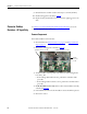
Gate Interface Board
See Chapter 1 - Component Diagrams and Torque Specifications to locate the
component
detailed in these instructions.
Remove Components
1. Read and follow the Safety Precautions on page 12 and Important Initial
Steps on page 13.
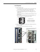
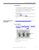
2. Remove the safety cover over the gate interface board.
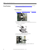
3. Label and disconnect all wires (J1 . . . J8).
4. Remove the four mounting nuts and remove the board.
Install Components
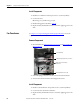
1. Install the new board. Torque the four mounting nuts to 1.8 N•m
(16 lb•in).
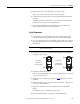
2. Connect J1 . . . J8 wires as shown above.
NOTE: J4 from the corresponding IGBT connects to J6 on the gate
interface board.
3. Replace all safety shields and enclosure covers before applying power to the
drive.
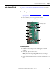
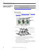
Gate Interface Board
Mounting Nuts (4)
J1
J2
J3
J5
J4
J6
J8
J7