
Manual

Rockwell Automation Publication 20B-IN024C-EN-P - June 2012 49
Component Replacement Procedures Chapter 3
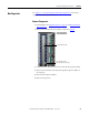
Inverter Power Module
(IGBT)
Kit includes:
Refer to the figures in Chapter 1 - Component Diagrams and Torque
Specifications for these instructions.
Remove Components
1. Read and follow the Safety Precautions on page 12 and Important Initial
Steps on page 13.
2. Remove the stacking panel as detailed on page 26
.
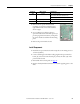
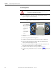
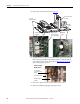
3. Remove the AC output busbar at the current transducer:
a. Remove and save the three bolts that secure the output busbar to the
AC output busbar and to the U, V or W busbar.
b. Remove and save the nut and threaded hex stud for the standoff.
c. Slide the output busbar to the right as far as it goes.
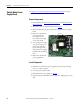
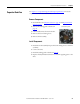
d. Remove and save the six screws that secure the AC output busbar to the
IGBT, and two nuts that secure the AC output busbar to its standoffs.
Remove and save the AC output busbar.
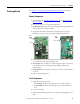
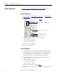
4. Remove transitional busbar assembly as detailed on page 28
.
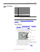
Qty. Component
1 IGBT module with circuit board
1 gate interface board
1 Gate interconnect harness
3 Flexible capacitor busbar, positive (+)
3 Flexible capacitor busbar, negative (-)
1 Tie down capacitor mount
3 Snubber capacitor
IMPORTANT
If any IGBT module is damaged, all IGBT modules and associated
components should be replaced. Perform the following procedure for
all IGBT modules.
Busbar Bolts (3)
Threaded Hex Stud and Nut