
Manual

48 Rockwell Automation Publication 20B-IN024C-EN-P - June 2012
Chapter 3 Component Replacement Procedures
Balancing Resistor
See Chapter 1 - Component Diagrams and Torque Specifications to locate the
component
detailed in these instructions.
Remove Components
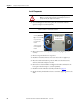
1. Read and follow the Safety Precautions on page 12 and Important Initial
Steps on page 13.
2. Remove the stacking panel as detailed on page 26
.
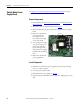
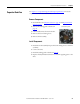
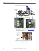
3. Label and disconnect all wires for the balancing resistor.
• Black: negative (–) busbar
• Yellow: bus capacitor busbar
• Blue: converter (+) busbar
4. Remove the two mounting screws.
5. Remove the balancing resistor.
Install Components
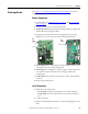
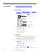
1. Use isopropyl alcohol to thoroughly clean the mounting surface of the
transitional busbar and the mounting surface of the new balancing resistor.
2. Apply thermal grease to the mounting surface of the new balancing
resistor. Torque the two mounting screws to 2.9 N•m (26 lb•in).
3. Connect the wires for the balancing resistor. Torque the three screws to
2.9 N•m (26 lb•in).
• Black: negative (–) busbar
• Yellow: bus capacitor busbar
• Blue: converter (+) busbar
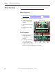
4. Install the stacking panel as detailed on page 27
.
5. Replace all safety shields and enclosure covers before applying power to the
drive.
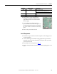
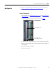
Screw for Resistor black wire
Screw for Resistor blue wire
Screw for Resistor yellow wire
Balancing Resistor and Mounting Screws