
Manual

44 Rockwell Automation Publication 20B-IN024C-EN-P - June 2012
Chapter 3 Component Replacement Procedures
DC Bus Filter Board
See Chapter 1 - Component Diagrams and Torque Specifications to locate the
component
detailed in these instructions.
Remove Components
1. Read and follow the Safety Precautions on page 12 and Important Initial
Steps on page 13.
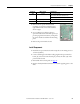
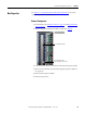
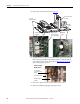
2. Remove the safety cover over the DC bus filter board.
3. Disconnect red and black
wires from TB1 and TB2
terminals.
4. Remove the four mounting
bolts.
5. Remove the DC bus filter
board.
Install Components
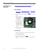
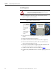
1. Install the new DC bus filter
board. Torque the four
mounting bolts to 1.7 N•m
(15 lb•in).
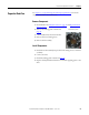
2. Connect the red and black
wires to TB1 and TB2
terminals as shown at right.
3. Replace all safety shields and
enclosure covers before applying power to the drive.
TB2 TB1
TB2-3
(red)
TB2-1
(black)
TB1-3
(red)
TB1-1
(black)
Mounting Bolts (4)