
Manual

Rockwell Automation Publication 20B-IN024C-EN-P - June 2012 43
Component Replacement Procedures Chapter 3
Precharge Board
See Chapter 1 - Component Diagrams and Torque Specifications to locate the
component
detailed in these instructions.
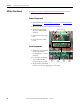
Remove Components
1. Read and follow the Safety Precautions on page 12 and Important Initial
Steps on page 13.
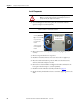
2. Remove the safety cover over the precharge board.
3. For DC input only: Verify that customer wiring to TB2 is properly labeled
and then disconnect wiring from TB2.
4. Using pliers if needed, remove the three wiring/harnesses (J1, J2, J3).
Note: Some connectors may not be labeled. Label them if needed.
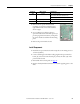
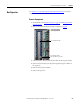
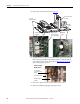
5. For AC input: Remove the precharge board mounting torx screw located
at the upper left corner of the precharge board.
6. For AC input: Use your fingers or needle-nose pliers to squeeze the tabs of
each of the three spacers and separate the precharge board from the
mounting plate.
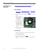
7. For DC input: Turn each of the six lock screws 1/4 turn counterclockwise
to unlock.
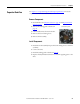
8. Remove the precharge board.
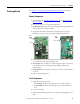
Install Components
1. Install the new precharge board.
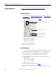
• For AC input: Torque the mounting screw to 1.7 N•m (15 lb•in).
• For DC input: Turn each of the six lock screws 1/4 turn clockwise to
lock.
2. Connect the wiring.
3. Replace all safety shields and enclosure covers before applying power to the
drive.
Spacers
Screw
AC
Input
Lock Screws (6)
DC
Input