
Manual

Rockwell Automation Publication 20B-IN024C-EN-P - June 2012 41
Component Replacement Procedures Chapter 3
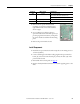
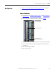
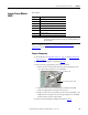
4. Remove the two power interface board
mounting torx screws located at the upper
right and lower left corners of the board as
shown at right.
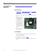
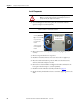
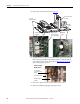
5. Use your fingers or needle-nose pliers to
squeeze the tabs of each of the nine spacers (see
previous page for their locations), and separate
the power interface board from the mounting
plate.
6. Remove the power interface board.
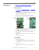
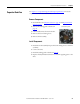
Install Components
1. Install the new power interface board. Torque the two mounting screws to
1.7 N•m (15 lb•in).
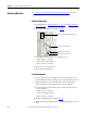
2. Connect all wiring. For the ribbon cable going from the power interface
board (J1) to the main control board (J2), connect the cable at J1 on the
power interface board.
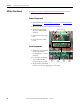
3. Reinstall the main control panel. See page 25
.
4. Replace all safety shields and enclosure covers before applying power to the
drive.
J24 red/black J1 on precharge board,
TB1 on DC bus filter board (AC input only)
TB1 on DC bus filter board (DC input only)
TB1 green/yellow PE on TB11
TB2 red #33, #34, and #35 on TB11
Connector Wire Color(s) Connects To: