
Manual

Rockwell Automation Publication 20B-IN024C-EN-P - June 2012 35
Chapter
3
Component Replacement Procedures
Overview
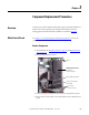
Component procedures detailed in this chapter apply to PowerFlex 700 Frame 8
drives for AC or DC input. Removal and replacement instructions for the
stacking panel and transitional busbar assemblies are detailed in Chapter 2
.
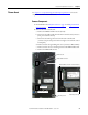
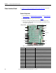
Main Control Board
See Chapter 1 - Component Diagrams and Torque Specifications to locate the
component
detailed in these instructions.
Remove Components
1. Read and follow the Safety Precautions on page 12 and Important Initial
Steps on page 13.
2. Remove safety shields as needed.
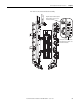
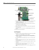
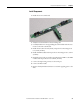
3. Unscrew the green/yellow ground wire from the communications panel.
4. Remove the two nuts and two screws and washers for the communications
panel.
Screw for green/yellow
Ground Wire
Release Cable from Clamp
Nuts (2)
Screws and
Washers (2 each)
Communications Panel
(Located over
main control panel)