
Manual

26 Rockwell Automation Publication 20B-IN024C-EN-P - June 2012
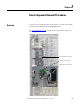
Chapter 2 Basic Component Removal Procedures
Stacking Panel
See Chapter 1 - Component Diagrams and Torque Specifications to locate the
component
detailed in these instructions.
Remove Components
1. Read and follow the Safety Precautions on page 12 and Important Initial
Steps on page 13.
2. Label and disconnect wiring as listed below.
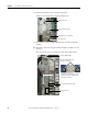
3. Disconnect the main control panel thermal sensor and wire located above
the main control board, from the wiring harness (see Figure 4 - on
page 18).
TIP
Remove the main control panel first to provide better access to wiring
and fasteners. See Main Control Panel on page 24
.
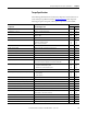
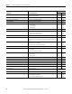
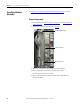
Connected
Component
Label on Wire
or Connector
Label on
Board
Notes
Precharge board J2, J3 J2, J3
DC bus filter board TB1 TB1
Power interface board J8 J8
J16 U U phase CT
J15 V V phase CT
J14 W W phase CT
J23 UP, VP, WP U, V, W positive gates
J18 UN, VN, WN U, V, W negative gates
J6 J6
TB11 Customer wiring Remove if not already done
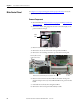
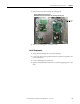
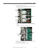
J2
J3
TB2
J8
J16…J14
J18
J23
J6
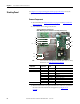
Shown without main control panel.
NOTE: Mounting position of boards on stacking panel may vary.
TB1
Precharge Board
Power
Interface
Board
DC Bus
Filter
Board