
Manual

24 Rockwell Automation Publication 20B-IN024C-EN-P - June 2012
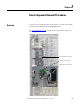
Chapter 2 Basic Component Removal Procedures
Main Control Panel
See Chapter 1 - Component Diagrams and Torque Specifications to locate the
component
detailed in these instructions.
Remove Components
1. Read and follow the Safety Precautions on page 12 and Important Initial
Steps on page 13.
2. Remove the ribbon cable going from the main control board (J2) to the
power interface board (J1).
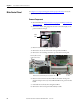
3. Disconnect the incoming ground wire to TB11.
4. Remove the two screws on the main control panel below TB11.
5. Remove the two mounting nuts at the top of the main control panel.
6. Disconnect the wire harnesses from TB11 to the switch mode power
supply board (J4 connector) and at TB1 and TB2 on the power interface
board.
7. Label and remove all customer wiring from TB11.
8. Remove the main control panel and carefully set aside.
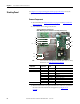
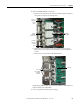
Ribbon
Cable
Mounting Nuts (2) at top
of Main Control Panel
Ground Wire
to TB11
MCP Mounting Screws (2) below TB11
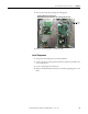
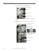
Mounting Nuts (2) at top
of Main Control Panel
Ground Wire
to TB11
MCP Mounting Screws (2) below TB11
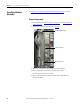
Mounting Nuts (2) at top
of Main Control Panel
Ground Wire
to TB11
Main Control Panel Mounting Screws (2) below TB11