
Manual

Rockwell Automation Publication 20B-IN024C-EN-P - June 2012 21
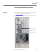
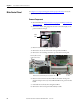
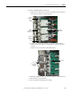
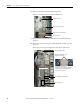
Component Diagrams and Torque Specifications Chapter 1
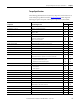
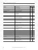
Torque Specifications
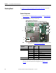
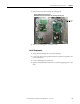
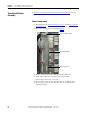
The following table lists fastener locations by component, how the fasteners are
used, and torque specifications. Refer to To rq u e S e q u e n c e
in this chapter for
fastening two-point, four-point, and six-point components to the heatsink.
Torque
Component Fastener Application N•m lb•in
20-Comm-x board fasten to HIM cradle/board 2.9 26
AC busbars (R, S, and T) fasten to converter SCR module 9 80
AC output busbar fasten to standoffs on heatsink
fasten to IGBT
5.6
5.6
50
50
Balancing resistor fasten to the transitional busbar 2.9 26
Balancing resistor wires black: negative (–) busbar
yellow: bus capacitor busbar
blue: converter (+) busbar
2.9
2.9
2.9
26
26
26
Busbars (DC+ and DC-) fasten upper busbar mounts to the converter busbars 23.5 208
Busbar mounting plate fasten the busbars to the bottom of the chassis 6 50
Busbar mounting plate bracket (left) fasten to the left side of the converter busbar 6 50
Bus capacitor busbar fasten to the capacitor setscrews (short) 5.6 50
Cables fasten +DC IN and +DC OUT cables to the transitional busbar 23.5 208
Capacitor bank fan fasten to chassis below the capacitor bank 1.8 16
Capacitor setscrews short setscrew fastens capacitor to the bus capacitor busbar
long setscrew fastens capacitor to the transitional busbar
0.7
0.7
6
6
Communications panel fasten to the main control panel
top of the communications panel
bottom of the communications panel
5.6
2.9
50
26
Converter busbars fasten to converter SCR modules 9 80
Converter power modules (SCR) – AC input only fasten to heatsink:
first sequence
final sequence
0.7
5.6
6
50
Converter SCR modules wiring fasten to the busbar connection at the SCR module 2.9 26
Converter snubber board – AC input only fasten to the standoffs on the converter busbars 2.9 26
Converter snubber resistors – AC input only fasten to the frame around the heatsink 2.9 26
Current transducer brackets fasten the mounting brackets to the current transducer 1.6 14
Current transducer assembly fasten to the backplane 2.9 26
DC bus filter board fasten to glastic standoffs on stacking panel 1.7 15
DC link choke – AC input only fasten mounting brackets to the bottom of the chassis
fasten cables to the choke connectors
9
9
80
80
Encoder board (optional) fasten to standoffs on main control board 2 14
Heatsink fan cover fasten to the back of the drive 2.9 26
Heatsink fan mounting plate fasten the heatsink fan to the fan mounting plate 2.9 26
Fan transformer fasten to the mounting plate below the capacitor bank fan 5.6 50