
Manual


16 Rockwell Automation Publication 20B-IN024C-EN-P - June 2012
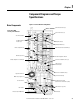
Chapter 1 Component Diagrams and Torque Specifications
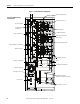
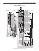
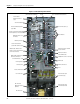
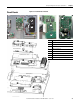
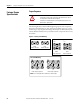
Figure 2 - Frame 8 DC Drive Components
Current Transducer (3)
Gate Interface Board (3)
Output Busbar (3)
Precharge Busbar (bottom)
Balancing Resistor
Snubber Capacitors for IGBTs (9)
Capacitor Bank Fan
IGBT Interface Board and
IGBT (3 each)
Flexible Capacitor
Busbars (18)
DC Bus Capacitor (18)
Motor Busbars (U, V, W)
Drive Shown With Stacking
Panel Removed
Tie Down Capacitor Mount
Precharge Resistors (2)
Busbar Mounting Plate
(Heatsink Fan is behind this plate)
Transitional Busbar
Precharge Fuse
Precharge Busbar (top)
Diode
Precharge SCR Module
AC Output Busbar (3)