Installation Instructions PowerFlex 700 Drive - Frame 8 Components Replacement
Important User Information Solid-state equipment has operational characteristics differing from those of electromechanical equipment. Safety Guidelines for the Application, Installation and Maintenance of Solid State Controls (publication SGI-1.1 available from your local Rockwell Automation® sales office or online at http://www.rockwellautomation.com/literature/) describes some important differences between solid-state equipment and hard-wired electromechanical devices.
Table of Contents Summary of Changes New and Updated Information . . . . . . . . . . . . . . . . . . . . . . . . . . . . . . . . . . . . . 7 Preface Introduction. . . . . . . . . . . . . . . . . . . . . . . . . . . . . . . . . . . . . . . . . . . . . . . . . . . . . . . 9 Component Kits . . . . . . . . . . . . . . . . . . . . . . . . . . . . . . . . . . . . . . . . . . . . . . . . . . . 9 Recommended Tools . . . . . . . . . . . . . . . . . . . . . . . . . . . . . . . . . . . . . . . . . . . . .
Table of Contents DC Bus Filter Board . . . . . . . . . . . . . . . . . . . . . . . . . . . . . . . . . . . . . . . . . . . . . . Remove Components . . . . . . . . . . . . . . . . . . . . . . . . . . . . . . . . . . . . . . . . . Install Components. . . . . . . . . . . . . . . . . . . . . . . . . . . . . . . . . . . . . . . . . . . Bus Capacitor . . . . . . . . . . . . . . . . . . . . . . . . . . . . . . . . . . . . . . . . . . . . . . . . . . . . Remove Components . . . . . . . . . . . . . . . . . . . . .
Table of Contents MOV Surge Suppressor - AC Input Only . . . . . . . . . . . . . . . . . . . . . . . . . . Remove Components. . . . . . . . . . . . . . . . . . . . . . . . . . . . . . . . . . . . . . . . . Install Components . . . . . . . . . . . . . . . . . . . . . . . . . . . . . . . . . . . . . . . . . . Precharge SCR Module and Diode - DC Input Only . . . . . . . . . . . . . . . . Remove Components. . . . . . . . . . . . . . . . . . . . . . . . . . . . . . . . . . . . . . . . . Install Components . . .
Table of Contents Notes: 6 Rockwell Automation Publication 20B-IN024C-EN-P - June 2012
Summary of Changes New and Updated Information This table contains the changes made to this revision. Topic Page Added additional resources table. 11 Updated the torque specifications table.
Summary of Changes Notes: 8 Rockwell Automation Publication 20B-IN024C-EN-P - June 2012
Preface Introduction This publication provides guidelines for replacing the major components in the PowerFlex® 700 Frame 8 drive. Component Kits All kits include necessary components, ESD wrist strap and hardware (if required), and thermal grease (if required). Description Printed Circuit Boards Gate Interface Board Precharge Board Kit Catalog No.
Preface Description Miscellaneous (continued) Bus Capacitor Kit Kit Catalog No. Notes SK-G1-BUSCAP1-F8 365A, 415A and 481A only. Includes one capacitor. Drive requires 18 kits. 535A and 600A only. Includes one capacitor. Drive requires 18 kits. Included with the kit for inverter power module (IGBT). Can be ordered separately. Includes: • Three positive flexible capacitor busbars • Three negative flexible capacitor busbars AC input.
Preface Recommended Tools The following list includes the most common tools used to disassemble and assemble the drive and components. This list may not include all the tools for your situation. Not all tools are needed for some components. Refer to the specific sections for details.
Preface Safety Precautions The precautions and general installation requirements provided in the PowerFlex 700 Frame 7 . . . 10 Installation Instructions (publication 20B-IN014) and the PowerFlex 700 User Manual (publication 20B-UM002) must be followed in addition to those included here. ATTENTION: To avoid an electric shock hazard, ensure that all power has been removed before proceeding. In addition, before servicing, verify that the voltage on the bus capacitors has discharged.
Preface ATTENTION: This assembly contains parts and sub-assemblies that are sensitive to electrostatic discharge. Static control precautions are required when servicing this assembly. Component damage may result if you ignore electrostatic discharge control procedures. If you are not familiar with static control procedures, refer to Guarding Against Electrostatic Damage, Allen-Bradley publication 8000-4.5.2, or any other applicable ESD protection handbook.
Preface Notes: 14 Rockwell Automation Publication 20B-IN024C-EN-P - June 2012
Chapter 1 Component Diagrams and Torque Specifications Drive Components Figure 1 - Frame 8 AC Drive Components Gate Interface Board (3) Drive Shown With Stacking Panel Removed Current Transducer (3) Transitional Busbar Flexible Capacitor Busbars (18) Output Busbar (3) AC Output Busbar (3) DC Bus Capacitor (18) IGBT Interface Board and IGBT (3) Balancing Resistor Tie Down Capacitor Mount Converter Snubber Resistors (3) Snubber Capacitors for IGBTs (9) SCR Converter Power Module Converter Snubb
Chapter 1 Component Diagrams and Torque Specifications Figure 2 - Frame 8 DC Drive Components Gate Interface Board (3) Drive Shown With Stacking Panel Removed Current Transducer (3) Transitional Busbar Flexible Capacitor Busbars (18) Output Busbar (3) AC Output Busbar (3) DC Bus Capacitor (18) IGBT Interface Board and IGBT (3 each) Tie Down Capacitor Mount Snubber Capacitors for IGBTs (9) Balancing Resistor Precharge Busbar (top) Diode Precharge SCR Module Precharge Busbar (bottom) Capacitor Bank F
Component Diagrams and Torque Specifications Chapter 1 Figure 3 - Frame 8 Busbars (AC Drive shown) DC+ Busbar DC- Busbar Transitional Busbar Assembly Rockwell Automation Publication 20B-IN024C-EN-P - June 2012 17
Chapter 1 Component Diagrams and Torque Specifications Figure 4 - Frame 8 (AC input drive shown) DC Capacitor Bank (Under Transitional Busbar) Gate Interface Board Heatsink Thermal Sensor Connector (J8 on each Gate Interface Board) DC Link Choke Output Connection (Top) Transitional Busbar Current Transducer (3) Inverter Snubber Capacitors (3 per IGBT) W Inverter Power Module IGBT (W) under Capacitors (V and U below W) V IGBT Gate Harness and CT Harness Motor Busbars U Balancing Resistor Power In
Component Diagrams and Torque Specifications Circuit Boards Chapter 1 Figure 5 - Circuit Boards on Frame 8 T-Comm Interface Communications Panel No.
Chapter 1 Component Diagrams and Torque Specifications Fastener Torque Specifications Torque Sequence ATTENTION: When mounting components to a drive’s heatsink, component fastener torque sequences and tolerances are crucial to component-to-heatsink heat dissipation. Components can be damaged if initial tightening procedure is not performed to specification. The following illustrates initial and final tightening sequences for components fastened to a heatsink using two, four, and six screws.
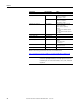
Component Diagrams and Torque Specifications Chapter 1 Torque Specifications The following table lists fastener locations by component, how the fasteners are used, and torque specifications. Refer to Torque Sequence in this chapter for fastening two-point, four-point, and six-point components to the heatsink. Torque Component Fastener Application N•m lb•in 20-Comm-x board fasten to HIM cradle/board 2.
Chapter 1 Component Diagrams and Torque Specifications Torque Component Fastener Application N•m lb•in Flexible capacitor busbars fasten to the transitional busbar fasten to the IGBT module 5.6 5.6 50 50 Gate interface board fasten to upright bracket on heatsink 1.8 16 Ground wire (green and yellow) from TB11 to the HIM cradle/board 1.6 14 HIM cradle/board fasten to the main control panel 2.9 26 IGBT module fasten to the heatsink: first sequence second sequence final sequence 0.7 2.
Chapter 2 Basic Component Removal Procedures Overview Component removal and replacement in this chapter are located on the stacking panel and transitional busbar assemblies highlighted below. See Circuit Boards on page 19 to identify the various panels that comprise the stacking panel assembly.
Chapter 2 Basic Component Removal Procedures Main Control Panel See Chapter 1 - Component Diagrams and Torque Specifications to locate the component detailed in these instructions. Remove Components 1. Read and follow the Safety Precautions on page 12 and Important Initial Steps on page 13. 2. Remove the ribbon cable going from the main control board ( J2) to the power interface board ( J1). Ribbon Cable 3. Disconnect the incoming ground wire to TB11. 4.
Basic Component Removal Procedures Chapter 2 Install Components 1. Replace any customer wiring to TB11. 2. Connect the wire harnesses from TB11 to the switch mode power supply board ( J4 connector) and at TB1 and TB2 on the power interface board. 3. Torque the two mounting nuts at the top of the main control panel to 5.6 N•m (50 lb•in). 4. Torque the two screws on the main control panel below TB11 to 2.9 N•m (26 lb•in). 5. Connect the incoming ground wire to TB11. 6.
Chapter 2 Basic Component Removal Procedures Stacking Panel See Chapter 1 - Component Diagrams and Torque Specifications to locate the component detailed in these instructions. Remove Components 1. Read and follow the Safety Precautions on page 12 and Important Initial Steps on page 13. 2. Label and disconnect wiring as listed below. Shown without main control panel. NOTE: Mounting position of boards on stacking panel may vary.
Basic Component Removal Procedures Chapter 2 4. Remove the six nuts for mounting the stacking panel. Shown without main control panel. NOTE: Mounting position of boards on stacking panel may vary. Mounting Nuts (6) 5. Remove the stacking panel; carefully set aside. Install Components 1. Torque the six mounting nuts to 5.6 N•m (50 lb•in). 2. Connect the main control panel thermal sensor and wire located above the main control board. 3. Connect all wiring that was removed. 4.
Chapter 2 Basic Component Removal Procedures Transitional Busbar Assembly See Chapter 1 - Component Diagrams and Torque Specifications to locate the component detailed in these instructions. Remove Components 1. Read and follow the Safety Precautions on page 12 and Important Initial Steps on page 13. 2. Remove the stacking panel as detailed on page 26. DC Choke Output Cables Transitional Busbar Balancing Resistor 3. If present, remove all customer wiring to transitional busbar. 4.
Basic Component Removal Procedures Chapter 2 6. Remove all IGBT Snubber components: a. Remove the six nuts that secure each set of snubber capacitors. Remove the capacitors, and save nuts and capacitors. Tie Down Capacitor Mount Screw Snubber Capacitor Mount Nuts Snubber Capacitors Tie Down Capacitor Mount Screw b. Remove the two screws that secure each tie down capacitor mount. Remove the tie down capacitor mounts and save screws and capacitor mounts. c.
Chapter 2 Basic Component Removal Procedures 8. Disconnect the yellow wire for the balancing resistor. You do not need to disconnect the blue and black wires. Balancing Resistor Resistor wiring tie wraps Balancing Resistor yellow wire Disconnect here 9. Remove the four side standoffs and brackets for the transitional busbar assembly. 10. Remove the 18 nuts fastening the transitional busbar assembly to the bus capacitors. The setscrews may come out with the nuts. Save all nuts and setcrews.
Basic Component Removal Procedures Chapter 2 11. Remove the transitional busbar assembly.
Chapter 2 Basic Component Removal Procedures Install Components See the photographs in the preceding Transitional Busbar Assembly section to identify any components discussed in this section. Positive (DC+) Flexible Capacitor Busbar (short) Negative (DC-) Flexible Capacitor Busbar (tall) IMPORTANT Each IGBT replacement kit includes three positive (DC+) and three negative (DC-) flexible capacitor busbars.
Basic Component Removal Procedures Chapter 2 6. Reinstall the screws for the four side standoffs and brackets to secure the transitional busbar assembly to the chassis. a. Torque the screws to 5.6 N•m (50 lb•in) to secure the brackets to the four red glastic spacers. b. Torque screws to 2.9 N•m (26 lb•in) to secure the two brackets to the drive chassis. 7. Torque the six setscrews for each IGBT board to 5.6 N•m (50 lb•in).
Chapter 2 Basic Component Removal Procedures Notes: 34 Rockwell Automation Publication 20B-IN024C-EN-P - June 2012
Chapter 3 Component Replacement Procedures Overview Component procedures detailed in this chapter apply to PowerFlex 700 Frame 8 drives for AC or DC input. Removal and replacement instructions for the stacking panel and transitional busbar assemblies are detailed in Chapter 2. Main Control Board See Chapter 1 - Component Diagrams and Torque Specifications to locate the component detailed in these instructions. Remove Components 1.
Chapter 3 Component Replacement Procedures 5. Disconnect both ribbon cables from the left side of the main control board. Ribbon Cable (1 of 2) Main Control Board Screws (4) Main Control Board TB11 Cable Connector Encoder Board (Optional) Encoder Board Screws (2); Hex standoffs (2) are between both boards 6. Hold the communications panel and release the cable at the bottom of the panel from its clamp (see previous page for its location) and set the communications panel aside. 7.
Component Replacement Procedures T-Comm Board Chapter 3 See Chapter 1 - Component Diagrams and Torque Specifications to locate the component detailed in these instructions. Remove Components 1. Read and follow the Safety Precautions on page 12 and Important Initial Steps on page 13. 2. Remove the main control board: a. Remove the HIM board from its slot (if used). b. Disconnect the ribbon cable from the main control board (connects to J1on power interface board). c.
Chapter 3 Component Replacement Procedures 3. Remove the 20-Comm-x board (if used): a. Disconnect the ribbon cable between the 20-Comm-x Board and T-Comm board; disconnect only from the T-Comm board. b. Remove and save the four mounting screws. 4. If the 20-Comm-x board is not used, remove the screw securing the T-Comm grounding tab. T-Comm grounding tab screw T-Comm grounding tab flat T-Comm grounding tab upright 5.
Component Replacement Procedures Chapter 3 Install Components 1. Install the new T-Comm board. 2. Verify the board is locked into all seven locking tabs. 3. Carefully bend the T-Comm grounding tab until it is flush with the screw mount on the main control board. 4. Install the 20-Comm-x board (if used). Torque the four mounting screws to 2.9 N•m (26 lb•in). 5. Install the HIM cradle/board. Torque the two mounting screws to 3 N•m (26 lb•in). 6.
Chapter 3 Component Replacement Procedures Power Interface Board See Chapter 1 - Component Diagrams and Torque Specifications to locate the component detailed in these instructions. Remove Components 1. Read and follow the Safety Precautions on page 12 and Important Initial Steps on page 13. 2. Remove the main control panel as detailed on page 24. 3.
Component Replacement Procedures Connector Wire Color(s) J24 red/black Chapter 3 Connects To: J1 on precharge board, TB1 on DC bus filter board (AC input only) TB1 on DC bus filter board (DC input only) TB1 green/yellow TB2 red PE on TB11 #33, #34, and #35 on TB11 4. Remove the two power interface board mounting torx screws located at the upper right and lower left corners of the board as shown at right. 5.
Chapter 3 Component Replacement Procedures Switch Mode Power Supply Board See Chapter 1 - Component Diagrams and Torque Specifications to locate the component detailed in these instructions. Remove Components 1. Read and follow the Safety Precautions on page 12 and Important Initial Steps on page 13. 2. Remove the main control panel as detailed on page 24. 3. Disconnect all cables ( J2, J4, J3, J1) from the switch mode power supply board. 4.
Component Replacement Procedures Precharge Board Chapter 3 See Chapter 1 - Component Diagrams and Torque Specifications to locate the component detailed in these instructions. Remove Components 1. Read and follow the Safety Precautions on page 12 and Important Initial Steps on page 13. 2. Remove the safety cover over the precharge board. 3. For DC input only: Verify that customer wiring to TB2 is properly labeled and then disconnect wiring from TB2. 4.
Chapter 3 Component Replacement Procedures DC Bus Filter Board See Chapter 1 - Component Diagrams and Torque Specifications to locate the component detailed in these instructions. Remove Components 1. Read and follow the Safety Precautions on page 12 and Important Initial Steps on page 13. 2. Remove the safety cover over the DC bus filter board. 3. Disconnect red and black wires from TB1 and TB2 terminals. Mounting Bolts (4) 4. Remove the four mounting bolts. 5. Remove the DC bus filter board.
Component Replacement Procedures Bus Capacitor Chapter 3 See Chapter 1 - Component Diagrams and Torque Specifications to locate the component detailed in these instructions. Remove Components 1. Read and follow the Safety Precautions on page 12 and Important Initial Steps on page 13. 2. Remove the transitional busbar assembly as detailed on page 28. Transitional Busbar Assembly Removed Bus Capacitor Busbar Bus Capacitor Busbar Nuts and Washers (18 each) 3.
Chapter 3 Component Replacement Procedures Install Components ATTENTION: Install each capacitor so its vent plug is at the top or 12 o’clock. Component and system damage may result if you position any bus capacitor incorrectly. 1. Use a 3 mm angle hex wrench to replace the setscrews for each new capacitor. Torque to 0.7 N•m (6 lb•in). IMPORTANT Each capacitor needs a short and long setscrew. See the illustration below for where to install each setscrew.
Component Replacement Procedures Capacitor Bank Fan Chapter 3 See Chapter 1 - Component Diagrams and Torque Specifications to locate the component detailed in these instructions. Remove Components 1. Read and follow the Safety Precautions on page 12 and Important Initial Steps on page 13. 2. Remove the stacking panel as detailed on page 26. Four Mounting Screw 3. Label and disconnect all wires for the fan. 4. Remove the four mounting screws. 5. Remove the fan assembly. Install Components 1.
Chapter 3 Component Replacement Procedures Balancing Resistor See Chapter 1 - Component Diagrams and Torque Specifications to locate the component detailed in these instructions. Remove Components 1. Read and follow the Safety Precautions on page 12 and Important Initial Steps on page 13. 2. Remove the stacking panel as detailed on page 26. Balancing Resistor and Mounting Screws Screw for Resistor black wire Screw for Resistor blue wire Screw for Resistor yellow wire 3.
Component Replacement Procedures Inverter Power Module (IGBT) Chapter 3 Kit includes: Qty. Component 1 IGBT module with circuit board 1 gate interface board 1 Gate interconnect harness 3 Flexible capacitor busbar, positive (+) 3 Flexible capacitor busbar, negative (-) 1 Tie down capacitor mount 3 Snubber capacitor IMPORTANT If any IGBT module is damaged, all IGBT modules and associated components should be replaced. Perform the following procedure for all IGBT modules.
Chapter 3 Component Replacement Procedures 5. Remove the Gate Interface board. See page 53. Current Transducer Assembly Tie Down Capacitor Mount Output Busbar Snubber Capacitors IGBT Gate Interface Board Assembly (not shown above) AC Output Busbar 6. Carefully examine the transitional busbar and bus capacitors for damage. When replacing any IGBT, Rockwell Automation recommends that you replace all bus capacitors. If needed, refer to Bus Capacitor on page 45 to replace damaged bus capacitors.
Component Replacement Procedures Chapter 3 Install Components 1. Install the IGBT module. a. Use isopropyl alcohol to thoroughly clean the mounting surface of the heatsink and the mounting surface of the new IGBT module. b. Use a 3- or 4-inch paint roller or putty knife to apply a thin, even coating of the supplied thermal grease to the mounting surface of the IGBT module. In the next step, take care to not disturb any of the thermal grease on the IGBT module. c.
Chapter 3 Component Replacement Procedures 3. Install the transitional busbar assembly. See page 32. Only torque nuts and screws after all components are in place. 4. Install the three supplied negative flexible capacitor busbars in positions 1, 3, and 5 on the IGBT. The negative flexible capacitor busbars have a higher angle. 5. Install the tie down capacitor mount: a. Insert the short ends of the six threaded studs with nuts through the flexible capacitor busbars and into the left side of the IGBT.
Component Replacement Procedures Gate Interface Board Chapter 3 See Chapter 1 - Component Diagrams and Torque Specifications to locate the component detailed in these instructions. Remove Components 1. Read and follow the Safety Precautions on page 12 and Important Initial Steps on page 13. 2. Remove the safety cover over the gate interface board. 3. Label and disconnect all wires ( J1 . . . J8). 4. Remove the four mounting nuts and remove the board.
Chapter 3 Component Replacement Procedures Current Transducer See Chapter 1 - Component Diagrams and Torque Specifications to locate the component detailed in these instructions. Remove Components 1. Read and follow the Safety Precautions on page 12 and Important Initial Steps on page 13. 2. Label and disconnect the wire from the transducer. 3. Remove the two 17 mm bolts and one 11 mm nut that connect the U, V, or W busbar to the output busbar. Current Transducer Transducer Brackets Output Busbar 4.
Component Replacement Procedures Chapter 3 7. Remove assembly by lifting the assembly up and turning it slightly counterclockwise while rotating the top of the output busbar toward you and around the U, V, or W busbar. 8. Move the busbar and transducer to an ESD-safe flat surface for working with it. 9. Separate the transducer from the brackets. Install Components 1. Mount brackets to the transducer. Torque screws to 1.6 N•m (14 lb•in). 2.
Chapter 3 Component Replacement Procedures Converter Power Module (SCR) AC Input Only If any converter SCR module fails, all three SCR modules should be replaced (kit includes three SCR modules). IMPORTANT See Chapter 1 - Component Diagrams and Torque Specifications to locate the component detailed in these instructions. Remove Components 1. Read and follow the Safety Precautions on page 12 and Important Initial Steps on page 13. 2. Remove the stacking panel as detailed on page 26.
Component Replacement Procedures Chapter 3 5. Disconnect the three AC busbars (R, S, T) at the top only. You do not need to remove the wires from the AC busbars. 6. Label and note the position of the converter SCR module leads. Remove the leads. Typically, the leads are marked as R, S, or T, and each is notched with the notch to the front of the converter SCR module. 7. Remove the four Phillips screws that hold each converter SCR to the heatsink and remove the converter SCR modules. Install Components 1.
Chapter 3 Component Replacement Procedures 9. Reinstall the DC+ and DC- busbars and torque to 9.0 N•m (80 lb•in). 10. Install stacking panel as detailed on page 27. 11. Replace all safety shields and enclosure covers before applying power to the drive. Converter Snubber Resistors - AC Input Only See Chapter 1 - Component Diagrams and Torque Specifications to locate the component detailed in these instructions. Remove Components Kit includes snubber board and resistor. 1.
Component Replacement Procedures Chapter 3 Install Components 1. Use isopropyl alcohol to thoroughly clean the mounting surface of the heatsink and the mounting surface of the new snubber resistor. 2. Use a 3-inch paint roller or putty knife to apply a thin even coating of the supplied thermal grease to the mounting surface of the new snubber resistor and install. Torque screws to 2.9 N•m (26 lb•in). 3. Connect the wires. 4.
Chapter 3 Component Replacement Procedures Install Components 1. Install the new snubber board. Torque screws to 2.9 N•m (26 lb•in). 2. Connect the wires. Black wire goes to J1. Blue wire goes to J2. 3. Install stacking panel as detailed on page 27. 4. Replace all safety shields and enclosure covers before applying power to the drive. Fan Transformer See Chapter 1 - Component Diagrams and Torque Specifications to locate the component detailed in these instructions. Remove Components 1.
Component Replacement Procedures Heatsink Fan - Removal from Back of Drive Chapter 3 The heatsink fan is located on the back of the drive. (For equipment clearance considerations, the fan can also be removed from the front of the drive. See Heatsink Fan - Removal from Front of Drive on page 63.) See Chapter 1 - Component Diagrams and Torque Specifications to locate the component detailed in these instructions. Remove Components 1.
Chapter 3 Component Replacement Procedures 6. Remove the fan. Fan Cover Screw Locations on Back of Drive Four on top and bottom for a total of eight Three on right side NOTE: No screws on left side Install Components 1. Install the new gasket (if the old gasket was damaged). 2. Place the fan assembly into the chassis but not installed in final position. Leave space for accessing fan cables from the front of the drive. Take care to not pinch wires. Fan Assembly (Front View), Removed from Drive 3.
Component Replacement Procedures Heatsink Fan - Removal from Front of Drive Chapter 3 The heatsink fan is located on the back of the drive. These instructions explain how to remove the fan from the front of the drive. Heatsink Fan behind mounting plate See Chapter 1 - Component Diagrams and Torque Specifications to locate the component detailed in these instructions. Remove Components 1. Read and follow the Safety Precautions on page 12 and Important Initial Steps on page 13. 2.
Chapter 3 Component Replacement Procedures Do not disconnect the U, V, or W busbars at the bottom. AC Drive Shown 17 mm bolt on DC+ Busbar 17 mm bolt on DC– Busbar Do not disconnect Busbars at the bottom. 5. Disconnect all busbars where they connect to the converter SCR modules with 16 mm bolts. Disconnect wiring. Do not disconnect the U, V, or W busbars at the bottom. AC Drive Shown 16 mm bolts Do not disconnect Busbars at the bottom.
Component Replacement Procedures Chapter 3 6. Disconnect the U, V, and W busbars at the top of each bar where they connect to the output busbars for the current transducers with two 17 mm bolts and one 11 mm nut. Do not remove the busbars from the setscrew on the output busbars at this time. Do not disconnect the U, V, or W busbars at the bottom. Output Busbar 17 mm bolts 11 mm nut Current Transducer Setscrew after 11 mm nut is removed 7. Remove the four 10 mm nuts for the busbars mounting plate.
Chapter 3 Component Replacement Procedures 8. Remove the entire busbar and mounting plate assembly. Set aside. 9. Unplug the fan cables. 10. For AC drives, remove the MOV surge suppressor as detailed on page 71. 11. Remove the left busbar mounting plate bracket. 12. Remove the 12 exterior screws on the fan mounting plate. Fan Mounting Plate Screws (12) Busbar Mounting Plate Bracket, Removed 13.
Component Replacement Procedures Chapter 3 Install Components 1. Remove the new fan housing from the new fan and mounting plate. Discard the new fan housing. 2. Install the new gasket (if the old gasket was damaged) and mounting plate to the chassis. Torque the mounting screws to 2.9 N•m (26 lb•in). 3. Install the left busbar mounting plate bracket. Torque the mounting screws to 5.6 N•m (50 lb•in). 4. For AC drives, install the MOV surge suppressor as detailed on page 71. 5. Connect the fan cables. 6.
Component Replacement Procedures Thermal Sensor wiring for both drives The thermal sensor system consists of: • A sensor secured to the upper mounting bracket for the main control panel. • A sensor secured to the heatsink above the SCR modules. • A connector to J8 on each of the three gate interface boards. A J8-U See Chapter 1 - Component Diagrams and Torque Specifications to locate the component detailed in these instructions.
Component Replacement Procedures Chapter 3 Remove Components 1. Read and follow the Safety Precautions on page 12 and Important Initial Steps on page 13. 2. Cut the wire ties for the wiring harness along the gate interface boards. 3. Note wire routing and location of sensors. 4. For the main control panel thermal sensor, remove the screw and nut on the main control panel and disconnect the other end from the wiring harness. IMPORTANT This screw and nut on the main control panel are small.
Chapter 3 Component Replacement Procedures DC Link Choke - AC Input Only See Chapter 1 - Component Diagrams and Torque Specifications to locate the component detailed in these instructions. Remove Components 1. Read and follow the Safety Precautions on page 12 and Important Initial Steps on page 13. +DC (Back/L2 Connector) –DC (Front/L3 Connector) +DC (Back/L1 Connector) –DC (Front/L4 Connector) DC Choke Connectors 2. Label and disconnect DC choke connectors. 3.
Component Replacement Procedures MOV Surge Suppressor AC Input Only Chapter 3 See Chapter 1 - Component Diagrams and Torque Specifications to locate the component detailed in these instructions. Remove Components 1. Read and follow the Safety Precautions on page 12 and Important Initial Steps on page 13. 2. Remove the stacking panel as detailed on page 26. MOV 3. Note wire placement and connections. Disconnect the MOV ground wire and the R, S, and T wires to the AC busbars. 4.
Chapter 3 Component Replacement Procedures Precharge SCR Module and Diode - DC Input Only See Chapter 1 - Component Diagrams and Torque Specifications to locate the component detailed in these instructions. Remove Components 1. Read and follow the Safety Precautions on page 12 and Important Initial Steps on page 13. 2. Remove the stacking panel as detailed on page 26. Diode SCR Precharge Wires (two places) Precharge Power Cables 3.
Component Replacement Procedures Chapter 3 WARNING: In the next step, be sure to properly install the modules as shown. If you install the SCR incorrectly, it will not work. If you install the diode incorrectly, then the drive and the bus capacitors may not operate properly and may prematurely fail. • The SCR (on the left) has a plug with prongs located at the bottom. • The diode (on the right) has a plug without prongs located at the top.
Chapter 3 Component Replacement Procedures Notes: 74 Rockwell Automation Publication 20B-IN024C-EN-P - June 2012
Rockwell Automation Support Rockwell Automation provides technical information on the Web to assist you in using its products. At http://www.rockwellautomation.com/support/, you can find technical manuals, a knowledge base of FAQs, technical and application notes, sample code and links to software service packs, and a MySupport feature that you can customize to make the best use of these tools.