
User Manual


Rockwell Automation Publication 20B-UM002G-EN-P - July 2014 95
Troubleshooting Chapter 2
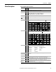
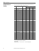
Table 9 - Motor and/or drive will not accelerate to commanded speed.
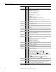
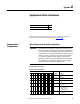
Table 10 - Motor operation is unstable.
Table 11 - Drive will not reverse motor direction.
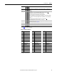
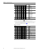
Table 12 - Stopping the drive results in a Decel Inhibit fault.
Cause(s) Indication Corrective Action
Acceleration time is excessive. None Reprogram [Accel Time x], see page 38
.
Excess load or short acceleration
times force the drive into current
limit, slowing or stopping
acceleration.
None Check [Drive Status 2], bit 10 to see if the drive is in
Current Limit (see page 47).
Remove excess load or reprogram [Accel Time x], see
page 38
.
Speed command source or value is
not as expected.
None Check for the proper Speed Command using Steps 1
through 7 above.
Programming is preventing the drive
output from exceeding limiting
values.
None Check [Maximum Speed], page 29
and [Maximum Freq]
page 24
to assure that speed is not limited by
programming.
Cause(s) Indication Corrective Action
Motor data was incorrectly entered
or Autotune was not performed.
None 1. Correctly enter motor nameplate data.
2. Perform “Static” or “Rotate” Autotune procedure,
see page 25.
Cause(s) Indication Corrective Action
Digital input is not selected for
reversing control.
None Check [Digital Inx Sel], page 63
. Choose correct input
and program for reversing mode.
Digital input is incorrectly wired. None Check input wiring.
Direction mode parameter is
incorrectly programmed.
None Reprogram [Direction Mode], page 44
for analog
“Bipolar” or digital “Unipolar” control.
Motor wiring is improperly phased
for reverse.
None Switch two motor leads.
A bipolar analog speed command
input is incorrectly wired or signal is
absent.
None 1. Use meter to check that an analog input voltage is
present.
2. Check wiring.
Positive voltage commands forward direction.
Negative voltage commands reverse direction.
Cause(s) Indication Corrective Action
The bus regulation feature is
enabled and is halting deceleration
due to excessive bus voltage. Excess
bus voltage is normally due to
excessive regenerated energy or
unstable AC line input voltages.
Internal timer has halted drive
operation.
Decel Inhibit fault
screen.
LCD Status Line
indicates “Faulted”.
1. See Attention statement on page 12
.
2. Reprogram parameters 161/162 to eliminate any
“Adjust Freq” selection.
3. Disable bus regulation (parameters 161 & 162) and
add a dynamic brake.
4. Correct AC input line instability or add an isolation
transformer.
5. Reset drive.