
User Manual


94 Rockwell Automation Publication 20B-UM002G-EN-P - July 2014
Chapter 2 Troubleshooting
Common Symptoms/
Corrective Actions
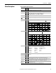
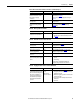
Table 6 - Drive does not Start from Start or Run Inputs wired to the terminal block.
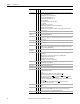
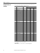
Table 7 - Drive does not Start from HIM.
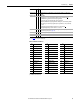
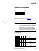
Table 8 - Drive does not respond to changes in speed command.
Cause(s) Indication Corrective Action
Drive is Faulted Flashing red status
light
Clear fault.
• Press Stop
• Cycle power
• Set [Fault Clear] to 1 (see page 52
)
• “Clear Faults” on the HIM Diagnostic menu
Incorrect input wiring. Refer to the
Installation Instructions for wiring
examples.
• 2 wire control requires Run, Run
Forward, Run Reverse or Jog
input.
• 3 wire control requires Start and
Stop inputs.
• Jumper from terminal 25 to 26 is
required.
None Wire inputs correctly and/or install jumper.
Incorrect digital input
programming.
• Mutually exclusive choices have
been made (i.e., Jog and Jog
Forward).
• 2 wire and 3 wire programming
can be conflicting.
• Exclusive functions (i.e,
direction control) can have
multiple inputs configured.
• Stop is factory default and is not
wired.
None Program [Digital Inx Sel] for correct inputs (page 63
).
Start or Run programming can be missing.
Flashing yellow status
light and “DigIn
CflctB” indication on
LCD HIM.
[Drive Status 2] shows
type 2 alarm(s).
Program [Digital Inx Sel] to resolve conflicts (page 63
).
Remove multiple selections for the same function.
Install stop button to apply a signal at stop terminal.
Cause(s) Indication Corrective Action
Drive is programmed for 2 wire
control. HIM Start button is
disabled for 2 wire control unless
param. 192, bit 1 = “1.”
None If 2 wire control is required, no action needed. See
[Save HIM Ref] on page 44
.
If 3 wire control is required, program [Digital Inx Sel]
for correct inputs (see page 63
).
Cause(s) Indication Corrective Action
No value is coming from the source
of the command.
LCD HIM Status Line
indicates “At Speed”
and output is 0 Hz.
1. If the source is an analog input, check wiring and
use a meter to check for presence of signal.
2. Check [Commanded Speed] for correct source (see
page 21
).
Incorrect reference source has been
programmed.
None 3. Check [Speed Ref Source] for the source of the
speed reference (see page 48
).
4. Reprogram [Speed Ref A Sel] for correct source (see
page 31
).
Incorrect Reference source is being
selected via remote device or digital
inputs.
None 5. Check [Drive Status 1], page 47, bits 12 and 13 for
unexpected source selections.
6. Check [Dig In Status], page 49 to see if inputs are
selecting an alternate source.
7. Reprogram digital inputs to correct “Speed Sel x”
option (see page 63
).