
User Manual

Rockwell Automation Publication 20B-UM002G-EN-P - July 2014 87
Troubleshooting Chapter 2
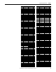
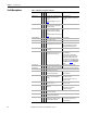
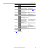
Ground Fault 13 1 A current path to earth ground greater
than 25% of drive rating.
Check the motor and external wiring to the
drive output terminals for a grounded
condition.
Hardware Fault 93 Hardware enable is disabled (jumpered
high) but logic pin is still low.
1. Check jumper.
2. Replace Main Control Board.
Hardware Fault 130 Gate array load error. 1. Cycle power.
2. Replace Main Control Board.
Hardware Fault 131 Dual port failure. 1. Cycle power.
2. Replace Main Control Board.
Hardware PTC 18 Motor PTC (Positive Temperature
Coefficient) Overtemp.
Heatsink LowTemp 10 1 Annunciates a too low temperature
case or an open NTC (heatsink
temperature sensing device) circuit.
1. Verify ambient temperature.
2. In cold ambient temperatures, add
space heaters.
Heatsink OvrTemp 8 1 Heatsink temperature exceeds 100% of
[Drive Temp] or is less than
approximately -19 °C.
1. Verify that maximum ambient
temperature has not been exceeded.
2. Check fan.
3. Check for excess load.
4. In cold ambient temperatures, add
space heaters.
HW OverCurrent 12 1 The drive output current has exceeded
the hardware current limit.
Check programming. Check for excess load,
improper DC boost setting, DC brake volts
set too high or other causes of excess
current.
Incompat MCB-PB 106 2 Drive rating information stored on the
power board is incompatible with the
main control board.
1. Load compatible version files into drive.
2. Frame 7…10 drives must have
firmware version 4.009 or greater.
I/O Comm Loss 121 I/O Board lost communications with the
Main Control Board.
Check connector. Check for induced noise.
Replace I/O board or Main Control Board.
I/O Failure 122 I/O was detected, but failed the
powerup sequence.
Replace Main Control Board.
Input Phase Loss 17 The DC bus ripple has exceeded a preset
level.
Check incoming power for a missing
phase/blown fuse.
IR Volts Range 77 “Calculate” is the autotune default and
the value determined by the autotune
procedure for IR Drop Volts is not in the
range of acceptable values.
Re-enter motor nameplate data.
IXo VoltageRange 87 Voltage calculated for motor inductive
impedance exceeds 25% of [Motor NP
Volts].
1. Check for proper motor sizing.
2. Check for correct programming of
[Motor NP Volts], parameter 41.
3. Additional output impedance can be
required.
Load Loss 15 Drive output torque current is below
[Load Loss Level] for a time period
greater than [Load Loss time].
1. Verify connections between motor and
load.
2. Verify level and time requirements.
Motor Overload 7 1
3
Internal electronic overload trip.
Enable/Disable with [Fault Config 1] on
page 52
.
An excessive motor load exists. Reduce
load so drive output current does not
exceed the current set by [Motor NP FLA].
Motor Thermistor 16 Thermistor output is out of range. 1. Verify that thermistor is connected.
2. Motor is overheated. Reduce load.
NVS I/O Checksum 109 EEprom checksum error. 1. Cycle power and repeat function.
2. Replace Main Control Board.
NVS I/O Failure 110 EEprom I/O error. 1. Cycle power and repeat function.
2. Replace Main Control Board.
Fault
No.
Type
(1)
Description Action
v6