
User Manual

84 Rockwell Automation Publication 20B-UM002G-EN-P - July 2014
Chapter 2 Troubleshooting
Drive Status
The condition or state of your drive is constantly monitored. Any changes will be
indicated through the LEDs and/or the HIM (if present).
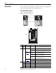
Front Panel LED Indications
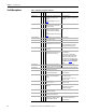
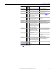
Figure 1 - Typical Drive Status Indicators
# Name Color State Description
1 PWR
(Power)
Green Steady Illuminates when power is applied to the drive.
2 STS
(Status)
Green Flashing Drive ready, but not running & no faults are present.
Steady Drive running, no faults are present.
Yel low
See page 91
Flashing,
Drive Stopped
A start inhibit condition exists, the drive cannot be started.
Check parameter 214 [Start Inhibits].
Flashing,
Drive Running
An intermittent type 1 alarm condition is occurring.
Check parameter 211 [Drive Alarm 1].
Steady,
Drive Running
A continuous type 1 alarm condition exists.
Check parameter 211 [Drive Alarm 1].
Red
See page 86
Flashing Fault has occurred. Check [Fault x Code] or Fault Queue.
Steady A non-resettable fault has occurred.
3 PORT Green – Status of DPI port internal communications (if present).
MOD Yellow – Status of communications module (when installed).
NET A Red – Status of network (if connected).
NET B Red – Status of secondary network (if connected).
Esc
7 8 9
4 5 6
1 2 3
.
0 +/-
Sel
Jog
Alt
POWER
STS
PORT
MOD
NET A
NET B
Exp
Param #
S.M.A.R.T.
Exit
Lang
Auto / Man
Remove
HOT surfaces can cause severe burns
CAUTION
Esc
7 8 9
4 5 6
1 2 3
.
0 +/-
Sel
Jog
Alt
POWER
STS
PORT
MOD
NET A
NET B
Exp
Param #
S.M.A.R.T.
Exit
Lang
Auto / Man
Remove
HOT surfaces can cause severe burns
CAUTION
TB11
TE
25 AMPERES RMS
MAXIMUM
Frames
7…10
1
2
3
1
3
2