
User Manual


64 Rockwell Automation Publication 20B-UM002G-EN-P - July 2014
Chapter 1 Programming and Parameters
INPUTS & OUTPUTS
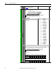
Digital Inputs
(15)
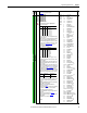
Adjust Voltage Select Inputs
(16)
Mixing selections 63-65 with 60-62 or 15-17 will
cause a type 2 alarm.
(17)
Firmware revision 10.001 and later.
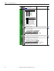
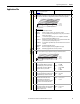
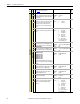
411 [DigIn DataLogic]
Provides data to the logical operations that will be done with the digital inputs when parameter
056 is set to option 9, “DigIn DatLog.”
056
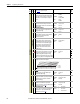
Digital Outputs
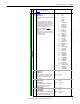
379 [Dig Out Setpt]
Sets the digital output value from a communication device.
Example: Set [Data In B1] to “379.” The first three bits of this value will determine the setting of
[Digital Outx Sel] which should be set to “30, Param Cntl.”
380
File
Group
No.
Parameter Name & Description
See page 16 for symbol descriptions
Values
Related
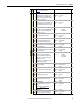
321AdjV Sel
0
0
0
0
1
1
1
1
0
0
1
1
0
0
1
1
0
1
0
1
0
1
0
1
Adj Volt Sel
Adj Volt Preset1
Adj Volt Preset2
Adj Volt Preset3
Adj Volt Preset4
Adj Volt Preset5
Adj Volt Preset6
Adj Volt Preset7
321AdjV Sel
0
0
0
0
1
1
1
1
0
0
1
1
0
0
1
1
0
1
0
1
0
1
0
1
Adj Volt Sel & Speed ref A Sel
Adj Volt Preset1 & Speed Ref B Sel
Adj Volt Preset2 & Speed Preset 2
Adj Volt Preset3 & Speed Preset 3
Adj Volt Preset4 & Speed Preset 4
Adj Volt Preset5 & Speed Preset 5
Adj Volt Preset6 & Speed Preset 6
Adj Volt Preset7 & Speed Preset 7
v6
000000xx000000xx
10 01234567891112131415
1 = Logical 1
0 = Logical 0
x = Reserved
Bit #
In1 ANDdata
In2 ANDdata
In3 ANDdata
In4 ANDdata
In5 ANDdata
In6 ANDdata
In1 ORdata
In2 ORdata
In3 ORdata
In4 ORdata
In5 ORdata
In6 ORdata
00x 0xxxxxxxxxxxx
10 01234567891112131415
1 = Output Energized
0 = Output De-energized
x = Reserved
Bit #
Digital Out1
Digital Out2
Digital Out3