
User Manual


Rockwell Automation Publication 20B-UM002G-EN-P - July 2014 63
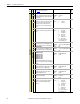
Programming and Parameters Chapter 1
File
Group
No.
Parameter Name & Description
See page 16 for symbol descriptions
Values
Related
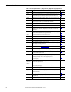
INPUTS & OUTPUTS
Digital Inputs
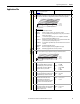
361
362
363
364
365
366
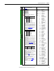
[Digital In1 Sel]
[Digital In2 Sel]
[Digital In3 Sel]
[Digital In4 Sel]
[Digital In5 Sel]
[Digital In6 Sel]
(10)
Selects the function for the digital inputs.
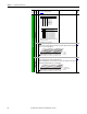
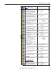
(1)
Speed Select Inputs
To access Preset Speed 1, set [Speed Ref x Sel] to
“Preset Speed 1”.
Type 2 Alarms - Some digital input programming
can cause conflicts that will result in a Type 2
alarm. Example: [Digital In1 Sel] set to “5, Start” in
3-wire control and [Digital In2 Sel] set to 7 “Run”
in2-wire. See Table 4 on page 91
for info on
resolving this type of conflict.
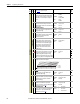
(3)
When [Digital Inx Sel] is set to option 2 “Clear
Faults” the Stop button cannot be used to clear a
fault condition.
(4)
Typical 3-Wire Inputs - Only 3-wire functions are
allowed. Including 2-wire selections will cause a
type 2 alarm.
(5)
Typical 2-Wire Inputs - Only 2-wire functions can
be chosen. Including 3-wire selections will cause a
type 2 alarm. See Table 4 on page 91 for conflicts.
(6)
Configures the input to command a transition
between the Manual/Auto or Auto/Manual speed
references. Manual/Auto” (68) is similar to “Auto/
Manual” (18) except that the polarity is opposite.
(7)
Opening an “Enable” input will cause the motor to
coast-to-stop, ignoring any programmed Stop
modes.
(8)
“Dig In ConflictB” alarm will occur if a “Start” input is
prog. without a “Stop” input.
(9)
Refer to the Sleep-Wake Mode Attention
statement on page 42
.
(10)
A dedicated hardware enable input is available via
a jumper selection. Refer to the Installation
Instructions for further information.
(11)
Only available when “Torque Proving” function is
selected.
(12)
Refer to Option Definitions on page 62.
(13)
Refer to [Dyn UsrSet Sel] on page 46 for selection
information.
(14)
Firmware v6.002 and later.
continued
Default:
Default:
Default:
Default:
Default:
Default:
Options:
4
5
18
15
16
17
0
1
2
3
4
5
6
7
8
9
10
11
12
13
14
15-17
18
19
20
21
22
23
24
25
26
27
28
29
30
31-33
34
35
36
37
38
39
40
41-42
43
44
45
46
47
48
49
50
51
52-56
57
58-59
60-62
63-65
66
67
68
69
70
“Stop – CF”
“Start”
“Auto/ Manual”
“Speed Sel 1”
“Speed Sel 2”
“Speed Sel 3”
“Not Used”
“Enable”
(7)(9)
“Clear Faults”(CF)
(3)
“Aux Fault”
“Stop – CF”
(9)
“Start”
(4) (8)
“Fwd/ Reverse”
(4)
“Run”
(5)(9)
“Run Forward”
(5)
“Run Reverse”
(5)
“Jog1”
“Jog Forward”
(5)
“Jog Reverse”
(5)
“Stop Mode B”
“Bus Reg Md B”
“Speed Sel 1-3”
(1)
“Auto/ Manual”
(6)
“Local”
“Acc2 & Dec2”
“Accel 2”
“Decel 2”
“MOP Inc”
(12)
“MOP Dec”
(12)
“Excl Link”
(12)
“PI Enable”
“PI Hold”
“PI Reset”
“Pwr Loss Lvl”
“Precharge En”
(12)
“Spd/Trq Sel1-3”
(2)
“Jog 2”
“PI Invert”
“Torque Setpt 1”
(12)
“Flt/MicroPos”
(11)(12)
“Fast Stop”
(12)
“Decel Limit”
“End Limit”
“UserSet Sel1-2”
(13)
“Run Level”
“RunFwd Level”
“RunRev Level”
(12)
“Run w/Comm”
(12)
“Hold Step”
(12)
“Redefine Pos”
(12)
“Find Home”
(12)
“Home Limit”
(12)
“Vel Override”
(12)
“Pos Sel 1-5”
(12)
“Prof Input”
(12)
“Reserved”
“AdjV Sel 1-3
(14)(15)
“AdjV/Hz Sel1-3
(14)(16)
“Abort Step”
(14)
“Abort Prof”
(14)
“Manual/Auto”
(6)
“MtrDC Inject”
(17)
“HOA Start”
(17)
100
156
162
096
141
143
195
194
380
124
321Auto Reference Source
0
0
0
0
1
1
1
1
0
0
1
1
0
0
1
1
0
1
0
1
0
1
0
1
Reference A
Reference B
Preset Speed 2
Preset Speed 3
Preset Speed 4
Preset Speed 5
Preset Speed 6
Preset Speed 7
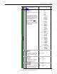
(2)
Speed/Torque Selection
321Spd/Trq Mode
0
0
0
0
1
1
1
1
0
0
1
1
0
0
1
1
0
1
0
1
0
1
0
1
Zero Torque
Spd Reg
Torque Reg
Min Spd/Trq
Max Spd/Trq
Sum Spd/Trq
Absolute
Pos/Spd Prof
Input
State
“Au to /M an ua l”
(18)
“Manual/Auto”
(68)
Lo
Hi
Auto
Manual
Manual
Auto