
User Manual

60 Rockwell Automation Publication 20B-UM002G-EN-P - July 2014
Chapter 1 Programming and Parameters
INPUTS & OUTPUTS
Analog Inputs
322
325
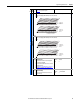
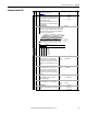
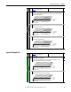
[Analog In 1 Hi]
[Analog In 2 Hi]
Sets the highest input value to the analog input x
scaling block.
[Anlg In Config], parameter 320 defines if this
input will be –/+10V or 0-20 mA.
Default:
Min/Max:
Units:
10.000 Volt
10.000 Volt
0.000/20.000mA
–/+10.000V
0.000/10.000V
0.001 mA
0.001 Volt
091
092
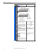
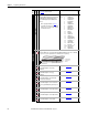
323
326
[Analog In 1 Lo]
[Analog In 2 Lo]
Sets the lowest input value to the analog input x
scaling block.
[Anlg In Config], parameter 320 defines if this
input will be –/+10V or 0-20 mA.
If set below 4 mA, [Analog In x Loss] should be
“Disabled.”
Default:
Min/Max:
Units:
0.000 Volt
0.000 Volt
0.000/20.000mA
–/+10.000V
0.000/10.000V
0.001 mA
0.001 Volt
091
092
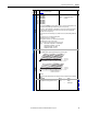
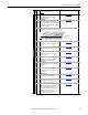
324
327
[Analog In 1 Loss]
[Analog In 2 Loss]
Selects drive action when an analog signal loss is
detected. Signal loss is defined as an analog
signal less than 1V or 2 mA. The signal loss event
ends and normal operation resumes when the
input signal level is greater than or equal to 1.5V
or 3 mA.
Note: parameter 190, [Direction Mode] must be
set to “0, Unipolar.”
Default:
Options:
0
0
0
1
2
3
4
5
6
“Disabled”
“Disabled”
“Disabled”
“Fault”
“Hold Input”
“Set Input Lo”
“Set Input Hi”
“Goto Preset1”
“Hold OutFreq”
091
092
Analog Outputs
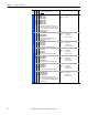
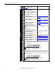
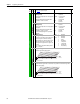
340 [Anlg Out Config]
Selects the mode for the analog outputs. .
341 [Anlg Out Absolut]
Selects whether the signed value or absolute value of a parameter is used before being scaled to
drive the analog output.
File
Group
No.
Parameter Name & Description
See page 16 for symbol descriptions
Values
Related
1xx 1xxxxxxxxxxxx
10 01234567891112131415
1 = Current
0 = Voltage
x = Reserved
Bit #
Factory Default Bit Values
Analog Out1
Analog Out2
1xx 1xxxxxxxxxxxx
10 01234567891112131415
1 = Absolute
0 = Signed
x = Reserved
Bit #
Factory Default Bit Values
Analog Out1
Analog Out2