
User Manual

Rockwell Automation Publication 20B-UM002G-EN-P - July 2014 59
Programming and Parameters Chapter 1
Inputs & Outputs File
COMMUNICATIONS
Security
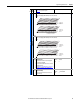
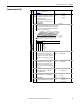
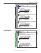
597 [Write Mask Act] Read Only
Status of write access for DPI ports. When bit 15 is set, network security is controlling the write
mask instead of [Write Mask Cfg].
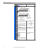
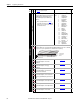
276 [Logic Mask]
Determines which ports can control the drive. If the bit for a port is set to “0,” the port will have
no control functions except for stop.
288
…
297
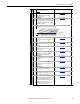
598 [Logic Mask Act] Read Only
Indicates status of the logic mask for DPI ports. When bit 15 is set, network security is controlling
the logic mask instead of [Logic Mask].
276
File
Group
No.
Parameter Name & Description
See page 16 for symbol descriptions
Values
Related
111 x111xxxxxxxx0
10 01234567891112131415
1 = Write Permitted
0 = Read Only
x = Reserved
Bit #
Factory Default Bit Values
DPI Port 1
DPI Port 2
DPI Port 3
DPI Port 4
DPI Port 5
DPI Port 6
(1)
Security
(1)
Firmware 6.002 and later.
1111111xxxxxxxxx
10 01234567891112131415
1 = Control Permitted
0 = Control Masked
x = Reserved
Bit #
Factory Default Bit Values
Digital In
DPI Port 1
DPI Port 2
DPI Port 3
DPI Port 4
DPI Port 5
DPI Port 6
(1)
(1)
Firmware 6.002 and later.
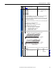
1111111xxxxxxxx0
10 01234567891112131415
1 = Control Permitted
0 = Control Masked
x = Reserved
Bit #
Factory Default Bit Values
Digital In
DPI Port 1
DPI Port 2
DPI Port 3
DPI Port 4
DPI Port 5
DPI Port 6
(1)
Security
(1)
Firmware 6.002 and later.
File
Group
No.
Parameter Name & Description
See page 16 for symbol descriptions
Values
Related
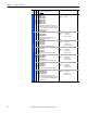
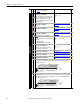
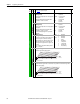
INPUTS & OUTPUTS
Analog Inputs
320 [Anlg In Config]
Selects the mode for the analog inputs.
For current mode, verify that wiring is correct at I/O terminals 17/18 (Analog In 1) or 19/20
(Analog In 2). Refer to the Installation Instructions for details.
322
325
323
326
321 [Anlg In Sqr Root]
Enables/disables the square root function for each input.
0xx 0xxxxxxxxxxxx
10 01234567891112131415
1 = Current
0 = Voltage
x = Reserved
Bit #
Factory Default Bit Values
An1 0=V 1=mA
An2 0=V 1=mA
0xx 0xxxxxxxxxxxx
10 01234567891112131415
1 = Enable
0 = Disable
x = Reserved
Bit #
Factory Default Bit Values
Analog In 1
Analog In 2