
User Manual

Rockwell Automation Publication 20B-UM002G-EN-P - July 2014 43
Programming and Parameters Chapter 1
DYNAMIC CONTROL
Restart Modes
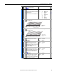
182 [Sleep Level]
Defines the analog input level that will stop the
drive.
Default:
Min/Max:
Units:
5.000 mA, 5.000 Volts
4.000 mA/[Wake Level]
0.000 Volts/[Wake Level]
0.001 mA
0.001 Volts
183
183 [Sleep Time]
Defines the amount of time at or below [Sleep
Level] before a Stop is issued.
Default:
Min/Max:
Units:
0.0 Secs
0.0/1000.0 Secs
0.1 Secs
182
Power Loss
177 [Gnd Warn Level]
Sets the level at which a ground warning fault
will occur. Configure with [Alarm Config 1].
Default:
Min/Max:
Units:
3.0 Amps
1.0/5.0 Amps
0.1 Amps
259
184 [Power Loss Mode]
Sets the reaction to a loss of input power. Power
loss is recognized when:
• DC bus voltage is ≤ 73% of [DC Bus Memory]
and [Power Loss Mode] is set to “Coast”.
• DC bus voltage is ≤ 82% of [DC Bus Memory]
and [Power Loss Mode] is set to “Decel”.
Default:
Options:
0
0
1
2
3
4
5
“Coast”
“Coast”
“Decel”
“Continue”
“Coast Input”
“Decel Input”
“Decel 2 Stop”
013
185
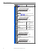
185 [Power Loss Time]
Sets the time that the drive will remain in power
loss mode before a fault is issued.
Default:
Min/Max:
Units:
0.5 Secs
0.0/60.0 Secs
0.1 Secs
184
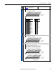
186 [Power Loss Level]
Sets the level at which the [Power Loss Mode]
selection will occur.
Default:
Min/Max:
Units:
Drive Rated Volts
0.0/999.9 VDC
0.1 VDC
The drive can use the percentages referenced in [Power Loss Mode] or a trigger point can be set
for line loss detection as follows:
V
trigger
= [DC Bus Memory] – [Power Loss Level]
A digital input (programmed to “29, Pwr Loss Lvl”) is used to toggle between fixed percentages
and the detection level.
187 [Load Loss Level]
Sets the percentage of motor nameplate torque
(absolute value) at which a load loss alarm will
occur.
Default:
Min/Max:
Units:
200.0%
0.0/800.0%
0.1%
211
259
188 [Load Loss Time]
Sets the time that current is below the level set in
[Load Loss Level] before a fault occurs.
Default:
Min/Max:
Units:
0.0 Secs
0.0/300.0 Secs
0.1 Secs
187
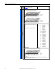
189 [Shear Pin Time]
Sets the time that the drive is at or above current
limit before a fault occurs. Zero disables this
feature.
Default:
Min/Max:
Units:
0.0 Secs
0.0/30.0 Secs
0.1 Secs
238
File
Group
No.
Parameter Name & Description
See page 16 for symbol descriptions
Values
Related
v6
ATTENTI ON: Drive damage can occur if proper input impedance is not
provided as explained below.
If the value for [Power Loss Level] is greater than 18% of [DC Bus Memory],
the user must provide a minimum line impedance to limit inrush current
when the power line recovers. The input impedance should be equal to or
greater than the equivalent of a 5% transformer with a VA rating 5 times
the drives input VA rating.