
User Manual

Rockwell Automation Publication 20B-UM002G-EN-P - July 2014 27
Programming and Parameters Chapter 1
MOTOR CONTROL
Torq Attributes
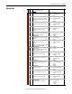
437 [Neg Torque Limit]
Defines the torque limit for the negative torque
reference value. The reference will not be
allowed to exceed this value.
Default:
Min/Max:
Units:
–200.0%
–800.0/0.0%
0.1%
053
438 [Torque Setpoint2]
Provides an internal fixed value for Torque
Setpoint when [Torque Ref x Sel] is set to “Torque
Setpt 2.”
Default:
Min/Max:
Units:
0.0%
–/+800.0%
0.1%
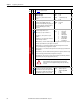
440 [Control Status]
Displays a summary status of any condition that can be
limiting either the current or the torque reference.
Read Only 053
441 [Mtr Tor Cur Ref]
Displays the torque current reference value that
is present at the output of the current rate limiter
(parameter 154).
Default:
Min/Max:
Units:
Read Only
–/+32767.0 Amps
0.01 Amps
053
Volts per Hertz
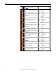
069 [Start/Acc Boost]
Sets the voltage boost level for starting and
acceleration when “Custom V/Hz” mode is
selected. Refer to parameter 083 [Overspeed
Limit].
Default:
Min/Max:
Units:
Based on Drive Rating
0.0/[Motor NP Volts] x 0.25
0.1 VAC
053
070
070 [Run Boost]
Sets the boost level for steady state or
deceleration when “Fan/Pmp V/Hz” or “Custom
V/Hz” modes are selected. See parameter 083
[Overspeed Limit].
Default:
Min/Max:
Units:
Based on Drive Rating
0.0/[Motor NP Volts] x 0.25
0.1 VAC
053
069
071 [Break Voltage]
Sets the voltage the drive will output at [Break
Frequency]. Refer to parameter 083 [Overspeed
Limit].
Default:
Min/Max:
Units:
[Motor NP Volts] x 0.25
0.0/[Motor NP Volts]
0.1 VAC
053
072
072 [Break Frequency]
Sets the frequency the drive will output at [Break
Voltage]. Refer to parameter 083.
Default:
Min/Max:
Units:
[Motor NP Hz] x 0.25
0.0/[Maximum Freq]
0.1 Hz
053
071
Speed Feedback
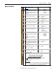
412 [Motor Fdbk Type]
Selects the encoder type; single channel or
quadrature. Options 1 & 3 detect a loss of
encoder signal (when using differential inputs)
regardless of the [Feedback Select], param. 080
setting. For FVC Vector mode, use a quadrature
encoder only (option 0/1). If a single channel
encoder is used (option 2/3) in sensorless vector
or V/Hz mode, select “Reverse Dis” (option 2) in
param. 190.
Default:
Options:
0
0
1
2
3
“Quadrature”
“Quadrature”
“Quad Check”
“Single Chan”
“Single Check”
File
Group
No.
Parameter Name & Description
See page 16 for symbol descriptions
Values
Related
FV
FV
FV
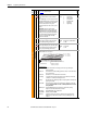
0000000000000000
10 01234567891112131415
1 = Condition True
0 = Condition False
x = Reserved
Bit #
NegTrqCurLim
PosTrqCurLim
NegFlxCurLim
PosFlxCurLim
NegTrqLimit
PosTrqLimit
NegPwrTrqLim
PosPwrTrqLim
Min Slip Lim
Max Slip Lim
MinTrqCurLim
VelTrqRef
TorqRef
FldWeakSts
Observe Sts
VltLimLeakag
00000xxxxxxxxxxx
26 161718192021222324252728293031
1 = Condition True
0 = Condition False
x = Reserved
Bit #
VltLimStator
DrvVoltLim
FluxBrake
Economize
RevPhaseMot
FV