
User Manual

Rockwell Automation Publication 20B-UM002G-EN-P - July 2014 131
Application Notes Appendix C
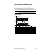
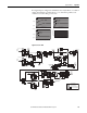
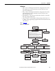
Example 2: Six Step Velocity Profile (Digital Input-Based)
In each step, the drive ramps at [Step x AccelTime] to [Step x Velocity] in the
direction of the sign of [Step x Velocity] until a digital input is detected. When
the input is detected it transitions to the next step in the profile. This continues
through Digital Input #6 activating step 5. Step 5 is defined as a “Parameter
Level” step. Digital Inputs used in the profile must be defined as “Prof Input.”
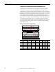
Figure 14 - Digital Input Example
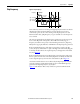
IMPORTANT
A transition is required to start each step. If the input is already true when
transitioning to a digital input step, the indexer will not go to the next step.
Step # [Step x Type] [Step x
Velocity]
[Step x
AccelTime]
[Step x
DecelTime]
[Step x
Value]
[Step x
Dwell]
[Step x
Batch]
[Step x
Next]
1 Digital Input 300 0.5 0.5 3.00 0.00 1 2
2 Digital Input 50 0.5 0.5 4.00 5.00 1 3
3 Digital Input -300 0.5 0.5 5.00 0.00 1 4
4 Digital Input -100 0.5 0.5 6.00 0.00 1 5
5 Param Level -50 0.5 0.5 701 0.00 1 6
6 End N/A N/A 0.5 N/A 0.00 N/A N/A
0
5
10
15
20
25
30
35
40
45
50
-350
-50
-150
-250
0
50
150
250
350
30 50 70 90 110 130 150 170
Step 1
Digital Input #4
Step 2
Step 3
Time
Step 4
Step 5
Note: Step 5 is a Parameter Level Step.
Step 6
Digital Input #6
5s
Dwell
[Encoder Speed], 415 [Units Traveled], 701 Current Step Dig In Status, 216[Profile Status], 700
Digital Input #3
Digital Input #5
10
Encoder Speed
Units Traveled
Profile Status (Scaled)
Current Step