
User Manual

Rockwell Automation Publication 20B-UM002G-EN-P - July 2014 101
Appendix B
HIM Overview
External & Internal
Connections
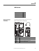
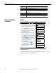
The PowerFlex 700 provides a number of cable connection points.
Figure 2 - Port Locations - Frames 0…6 (0 Frame shown).
Topic Page
External & Internal Connections 101
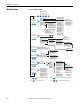
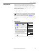
Menu Structure 104
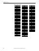
Viewing and Editing Parameters 106
Removing/Installing the HIM 102
No. Connector Description
1 DPI Port 1 HIM connection when installed in cover.
2 DPI Port 2 Cable connection for handheld and remote options.
3 DPI Port 3 or 2 Splitter cable connected to DPI Port 2 provides additional port.
4 DPI Port 5 Cable connection for communications adapter.
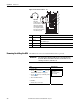
BR1
BR2
DC+
DC–
PE
U/T1
V/T2
W/T3
R/L1
S/L2
T/L3
Optional
Communications
Module
Use 75C Wire Only
#10-#14 AWG
Torque to 7 in-lbs
!
DANGER
2
1or3
1
4
2
3