User Manual PowerFlex 700 AC Drives – Frames 0…10 Vector Control Firmware 4.
Important User Information Read this document and the documents listed in the additional resources section about installation, configuration, and operation of this equipment before you install, configure, operate, or maintain this product. Users are required to familiarize themselves with installation and wiring instructions in addition to requirements of all applicable codes, laws, and standards.
Summary of Changes The information below summarizes the changes to the PowerFlex 700 User Manual, publication 20B-UM002 since the last release. New and Updated Information Manual Updates Description of New or Updated Information Page Removed the product certifications and specifications from Appendix A. All certification and specification information is located in the PowerFlex 700 Adjustable Frequency AC Drive Technical Data, publication 20BTD001.
Summary of Changes Notes: 4 Rockwell Automation Publication 20B-UM002G-EN-P - July 2014
Table of Contents Preface Who Should Use this Manual? . . . . . . . . . . . . . . . . . . . . . . . . . . . . . . . . . . . . . . 9 What Is Not in this Manual. . . . . . . . . . . . . . . . . . . . . . . . . . . . . . . . . . . . . . . . . 9 Manual Conventions . . . . . . . . . . . . . . . . . . . . . . . . . . . . . . . . . . . . . . . . . . . . . . . 9 Additional Resources . . . . . . . . . . . . . . . . . . . . . . . . . . . . . . . . . . . . . . . . . . . . . 10 ATEX Approved Drives & Motors . . . . .
Table of Contents Appendix B HIM Overview External & Internal Connections . . . . . . . . . . . . . . . . . . . . . . . . . . . . . . . . . Removing/Installing the HIM. . . . . . . . . . . . . . . . . . . . . . . . . . . . . . . . . . . . Disconnecting the HIM. . . . . . . . . . . . . . . . . . . . . . . . . . . . . . . . . . . . . . Reconnecting the HIM . . . . . . . . . . . . . . . . . . . . . . . . . . . . . . . . . . . . . . Menu Structure . . . . . . . . . . . . . . . . . . . . . . . . . . . . . . .
Table of Contents Example 3: Five Step Positioner with Incremental Encoder . . . . . Power Loss Ride Through . . . . . . . . . . . . . . . . . . . . . . . . . . . . . . . . . . . . . . . Process PID . . . . . . . . . . . . . . . . . . . . . . . . . . . . . . . . . . . . . . . . . . . . . . . . . . . . PI Enable . . . . . . . . . . . . . . . . . . . . . . . . . . . . . . . . . . . . . . . . . . . . . . . . . . . Reverse Speed Limit . . . . . . . . . . . . . . . . . . . . . . . . . . . . . . . . . . . . . .
Table of Contents 8 Rockwell Automation Publication 20B-UM002G-EN-P - July 2014
Preface The purpose of this manual is to provide you with the basic information needed to program and troubleshoot the PowerFlex 700 Adjustable Frequency AC Drive with Vector Control. Topic Page Who Should Use this Manual? 9 What Is Not in this Manual 9 Manual Conventions 9 Additional Resources 10 ATEX Approved Drives & Motors 10 Drive Frame Sizes 10 General Precautions 11 Catalog Number Explanation 13 Who Should Use this Manual? This manual is intended for qualified personnel.
Preface Additional Resources These documents contain additional information concerning related products from Rockwell Automation. Resource Description PowerFlex 700 Standard Control User Manual, publication 20B-UM001 Provides detailed information on: • Parameters and programming • Faults, alarms, and troubleshooting PowerFlex 700 AC Drive Technical Data, publication 20B-TD001 This publication provides detailed drive specifications, option specifications and input protection device ratings.
Preface General Precautions ATTENTION: This drive contains ESD (Electrostatic Discharge) sensitive parts and assemblies. Static control precautions are required when installing, testing, servicing or repairing this assembly. Component damage can result if ESD control procedures are not followed. If you are not familiar with static control procedures, reference A-B publication 8000-4.5.2, “Guarding Against Electrostatic Damage” or any other applicable ESD protection handbook.
Preface ATTENTION: The “adjust freq” portion of the bus regulator function is extremely useful for preventing nuisance overvoltage faults resulting from aggressive decelerations, overhauling loads, and eccentric loads. It forces the output frequency to be greater than commanded frequency while the drive's bus voltage is increasing towards levels that would otherwise cause a fault. However, it can also cause either of the following two conditions to occur.
Preface Catalog Number Explanation 20B D 2P1 A 3 A Y N A E C 0 NN AD a b c1…c5 d e f g h i j k l m n a c2 c3 Drive ND Rating ND Rating Code Type 20B PowerFlex 700 400V, 50 Hz Input b Voltage Rating Code Voltage Ph. Prechg.
Preface 20B D 2P1 A 3 A Y N A E C 0 NN AD a b c1…c5 d e f g h i j k l m n c5 f k ND Rating Documentation Control & I/O Code Type Code Control I/O Volts Code Amps 690V, 50 Hz Input kW Frame A Manual A Standard ♦ 24V DC/AC 052 52 45 5 N No Manual B Standard ♦ 115V AC 060 60 55 5 Q C Vector Δ 24V DC 082 82 75 5 No Shipping Package (Internal Use Only) D Vector Δ 115V AC N Standard None 098 98 90 6 119 119 110 6 142 142 132 6
Chapter 1 Programming and Parameters This chapter provides a complete listing and description of the PowerFlex 700 parameters. The parameters can be programmed (viewed/edited) using an LCD HIM (Human Interface Module). As an alternative, programming can also be performed using DriveExplorer™ or DriveExecutive™ software and a personal computer. See Appendix B for a brief description of the LCD HIM.
2 Group No. Drive . . . 3 4 Parameter Name & Description 5 Values Default: 198 [Load Frm Usr Set] Loads a previously saved set of parameter values Options: from a selected user set location in drive nonvolatile memory to active drive memory. 7 8 0 199 “Ready” “Ready” 0 “User Set 1” 1 “User Set 2” 2 “User Set 3” 3 Read Only 361 … 366 D ig it D i g al In6 it D i g al In5 ital D i g In4 it D i g al In3 it D i g al In2 ital In1 Diagnostics 216 [Dig In Status] Status of the digital inputs.
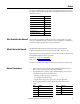
Programming and Parameters How Parameters are Organized Chapter 1 The LCD HIM displays parameters in a File-Group-Parameter or Numbered List view order. To switch display mode, access the Main Menu, press ALT, then Sel while cursor is on the parameter selection. In addition, using [Param Access Lvl], the user has the option to display the full parameter set (Advanced), commonly used parameters (Basic) or diagnostic/advanced tuning parameters (Reserved).
Chapter 1 Programming and Parameters Basic Parameter View Parameter 196 [Param Access Lvl] set to option 0 “Basic.
Programming and Parameters Chapter 1 Advanced Parameter View Parameter 196 [Param Access Lvl] set to option 1 “Advanced.
Chapter 1 Programming and Parameters File Utility Group Direction Config HIM Ref Config MOP Config Drive Memory Utility Diagnostics Faults Alarms Scaled Blocks Communication Comm Control Comm unica tion Masks & Owners Datalinks Security Inputs & Outputs Analog Inputs Inputs & Outpu ts Analog Outputs Digital Inputs Digital Outputs Applications Applica Torq Proving tions Adjust Voltage Oil Well Pump Pos/Spd Profile ProfSetup/Status Profile /Indexe r Profile Step 1-16 Parameters Direc
Metering MONITOR Values See page 16 for symbol descriptions 001 [Output Freq] Output frequency present at T1, T2 & T3 (U, V & W) 002 [Commanded Speed] Value of the active Speed/Frequency Reference. Displayed in Hz or RPM, depending on value of [Speed Units]. 003 [Output Current] The total output current present at T1, T2 & T3 (U, V & W). 004 [Torque Current] Based on the motor, the amount of current that is in phase with the fundamental voltage component.
Values See page 16 for symbol descriptions 018 [PTC HW Value] Default: Value present at the drive's PTC input terminals. Min/Max: Units: 021 [Spd Fdbk No Filt] Default: Displays the unfiltered value of the actual motor Min/Max: speed, whether measured by encoder feedback or estimated. Units: 022 [Ramped Speed] Value of commanded speed after Accel/Decel, and S-Curve are applied. Default: Min/Max: Drive Data MONITOR Metering Units: 22 Related Parameter Name & Description No.
Motor Data MOTOR CONTROL Values See page 16 for symbol descriptions 040 [Motor Type] Set to match the type of motor connected. (1) Important: Selecting option 1 or 2 also requires selection of “Custom V/Hz,” option 2 in parameter 53. 041 [Motor NP Volts] Set to the motor nameplate rated volts. Default: 0 “Induction” Options: 0 1 2 “Induction” “Synchr Reluc” (1) “Synchr PM” (1) Default: Based on Drive Rating Min/Max: Units: Default: 0.0/[Rated Volts] 0.
Values Related No. Parameter Name & Description See page 16 for symbol descriptions 053 [Motor Cntl Sel] Sets the method of motor control used in the drive. When “Adj Voltage” is selected, voltage control is independent from frequency control. The voltage and frequency components have independent references and accel/decel rates. Typical applications include non-motor loads or power supplies. Important: “FVC Vector” mode requires autotuning of the motor.
Chapter 1 Values See page 16 for symbol descriptions Torq Attributes MOTOR CONTROL “Manual” 057 [Flux Up Mode] Default: 0 Auto = Flux is established for a calculated time Options: “Manual” 0 period based on motor nameplate data. [Flux Up “Automatic” 1 Time] is not used. Manual = Flux is established for [Flux Up Time] before acceleration. 0.000 Secs 058 [Flux Up Time] Default: Sets the amount of time the drive will use to try Min/Max: 0.000/5.000 Secs and achieve full motor stator flux.
Values Related Parameter Name & Description No. Group Programming and Parameters File Chapter 1 See page 16 for symbol descriptions 064 [Ixo Voltage Drop] Value of voltage drop across the leakage inductance of the motor at rated motor current. Used only when parameter 53 is set to “Sensrls Vect,” “SV Economize or “FVC Vector.” 066 [Autotune Torque] Specifies motor torque applied to the motor during the flux current and inertia tests FV performed during an autotune.
Values See page 16 for symbol descriptions 437 [Neg Torque Limit] Default: Defines the torque limit for the negative torque Min/Max: FV reference value. The reference will not be Units: allowed to exceed this value. 438 [Torque Setpoint2] Default: Min/Max: FV Provides an internal fixed value for Torque Setpoint when [Torque Ref x Sel] is set to “Torque Units: Setpt 2.” 440 [Control Status] FV Displays a summary status of any condition that can be limiting either the current or the torque reference. –200.
Values See page 16 for symbol descriptions 413 [Encoder PPR] Contains the encoder pulses per revolution. For improved operation in FVC Vector mode, PPR should be ³ (64 x motor poles). 414 [Enc Position Fdbk] Displays raw encoder pulse count. For single channel encoders, this count will increase (per rev.) by the amount in [Encoder PPR]. For quadrature encoders this count will increase by 4 times the amount defined in [Encoder PPR]. A power cycle is required to reset this value.
Values Chapter 1 Related Parameter Name & Description No. File Speed Command File Group Programming and Parameters See page 16 for symbol descriptions Default: 079 [Speed Units] Selects the units to be used for all speed related Options: parameters. Options 0 & 1 indicate status only. 2 & 3 will convert/configure the drive for that selection.
Values Related Parameter Name & Description No. Group Programming and Parameters File Chapter 1 See page 16 for symbol descriptions 084 [Skip Frequency 1] 085 [Skip Frequency 2] 086 [Skip Frequency 3] Sets a frequency at which the drive will not operate. 087 [Skip Freq Band] Determines the bandwidth around a skip frequency. [Skip Freq Band] is split, applying 1/2 above and 1/2 below the actual skip frequency. The same bandwidth applies to all skip frequencies.
Values See page 16 for symbol descriptions 090 [Speed Ref A Sel] Default: Selects the source of the speed reference to the Options: drive unless [Speed Ref B Sel] or [Preset Speed 17] is selected. (1) See Appendix B for DPI port locations. If selected, HIM manual control is not allowed. (3) Minimum 64 PPR required. Speed References (2) SPEED COMMAND Chapter 1 Related Parameter Name & Description No.
Values See page 16 for symbol descriptions 096 [TB Man Ref Sel] Default: Sets the manual speed reference source when a Options: digital input (parameter 361…366) is configured for “Auto/Manual” or “Manual/Auto” (v7.002 & later). (1) Discrete Speeds SPEED COMMAND Speed References (2) 32 Related Parameter Name & Description No.
Parameter Name & Description Values See page 16 for symbol descriptions 108 [Jog Speed 2] Sets the output frequency when Jog Speed 2 is selected. Default: 10.0 Hz 300.0 RPM Min/Max: Units: 116 [Trim % Setpoint] Adds or subtracts a percentage of the speed reference or maximum speed. Dependent on the setting of [Trim Out Select], parameter 118. 117 [Trim In Select] Specifies which analog input signal is being used as a trim input. Default: –/+[Maximum Speed] 0.1 Hz 1 RPM 0.
Values Related Parameter Name & Description No. Group Programming and Parameters File Chapter 1 See page 16 for symbol descriptions Slip Comp Important: Parameters in the Slip Comp Group are used to enable and tune the Slip Compensation Regulator. In order to allow the regulator to control drive operation, parameter 080 [Speed Mode] must be set to 1 “Slip Comp”. 121 [Slip RPM @ FLA] Sets the amount of compensation to drive output at motor FLA.
See page 16 for symbol descriptions 126 [PI Reference Sel] Selects the source of the PI reference. (1) 0 Options: “PI Setpoint” 0 “Analog In 1” 1 “Analog In 2” 2 3-6 “Reserved” “Pulse In” 7 “Encoder” 8 “MOP Level” 9 “Master Ref” 10 11-17 “Preset Spd1-7” 18-22 “DPI Port 1-5” 23-24 “Reserved” 25-28 “Scale Block 1-4” “Preset1-7 Volt” (1) 29 36 “Voltage Cmd” (1) 50.00% Default: Min/Max: Units: Default: Default: Min/Max: Units: 0.00/100.00 Secs 0.01 Secs Default: 1.0 Min/Max: Units: Default: 0.00/100.
Values Related Parameter Name & Description No. Group Programming and Parameters File Chapter 1 See page 16 for symbol descriptions 132 [PI Upper Limit] Sets the upper limit of the PI output. Default: +[Maximum Freq] 100% Min/Max: –/+400.0 Hz –/+800.0% 0.1 Hz 0.1% 0.0 Hz 100.0% Units: 133 [PI Preload] Sets the value used to preload the integral component on start or enable.
Values See page 16 for symbol descriptions 445 [Ki Speed Loop] FV Controls the integral error gain of the speed regulator. The drive automatically adjusts [Ki Speed Loop] when a non-zero value is entered for [Speed Desired BW] or an autotune is performed. Typically, manual adjustment of this parameter is needed only if system inertia cannot be determined through an autotune. [Speed Desired BW] is set to “0” when a manual adjustment is made to this parameter.
Programming and Parameters Ramp Rates Load Limits Related Values See page 16 for symbol descriptions 140 [Accel Time 1] 141 [Accel Time 2] Sets the rate of accel for all speed increases. Max Speed = Accel Rate Accel Time Default: 10.0 Secs 10.0 Secs Min/Max: Units: 0.0/3600.0 Secs 0.1 Secs 142 [Decel Time 1] 143 [Decel Time 2] Sets the rate of decel for all speed decreases. Max Speed = Decel Rate Decel Time Default: 10.0 Secs 10.0 Secs Min/Max: Units: 0.0/3600.0 Secs 0.
Values See page 16 for symbol descriptions 153 [Regen Power Limit] FV Sets the maximum power limit allowed to transfer from the motor to the DC bus. When using an external dynamic brake, set this parameter to its maximum value. 154 [Current Rate Limit] FV Sets the largest allowable rate of change for the current reference signal. This number is scaled in percent of maximum motor current every 250 microseconds. 145 [DB While Stopped] Enables/disables dynamic brake operation when drive is stopped.
Values Related Parameter Name & Description No. Group Programming and Parameters File Chapter 1 See page 16 for symbol descriptions 161 [Bus Reg Mode A] Default: 162 [Bus Reg Mode B] Sets the method and sequence of the DC bus Options: regulator voltage. Choices are dynamic brake, frequency adjust or both. Sequence is determined by programming or digital input to the terminal block.
Values See page 16 for symbol descriptions 167 [Powerup Delay] Defines the programmed delay time, in seconds, before a start command is accepted after a power up. 168 [Start At PowerUp] Enables/disables a feature to issue a Start or Run command and automatically resume running at commanded speed after drive input power is restored. Requires a digital input configured for Run or Start and a valid start contact. Chapter 1 Related Parameter Name & Description No.
Values Related Parameter Name & Description No. Group Programming and Parameters File Chapter 1 See page 16 for symbol descriptions 178 [Sleep-Wake Mode] Default: Enables/disables the Sleep/Wake function. Options: Important: When enabled, the following conditions must be met: • A proper value must be programmed for [Sleep Level] & [Wake Level]. • A speed reference must be selected in [Speed Ref A Sel].
Chapter 1 Values Related Parameter Name & Description No. Group Power Loss DYNAMIC CONTROL Restart Modes File Programming and Parameters See page 16 for symbol descriptions 182 [Sleep Level] Default: Defines the analog input level that will stop the Min/Max: drive. Units: 5.000 mA, 5.000 Volts 183 4.000 mA/[Wake Level] 0.000 Volts/[Wake Level] 0.001 mA 0.001 Volts 0.0 Secs 182 183 [Sleep Time] Default: Defines the amount of time at or below [Sleep Min/Max: 0.0/1000.
Programming and Parameters Values Related No. Parameter Name & Description See page 16 for symbol descriptions 190 [Direction Mode] Selects method for changing direction.
Chapter 1 Values Related Parameter Name & Description No. Group File Programming and Parameters See page 16 for symbol descriptions MOP Config At S t At P op ow r Do wn 194 [Save MOP Ref] Enables/disables the feature that saves the present MOP frequency reference at power down or at stop. x x x x x x x x x x x x x x 0 0 15 14 13 12 11 10 9 8 7 6 5 4 3 2 1 0 Bit # Factory Default Bit Values 195 [MOP Rate] Sets rate of change of the MOP reference in response to a digital input. Default: 1.
Values Related Parameter Name & Description No. Group Programming and Parameters File Chapter 1 See page 16 for symbol descriptions 0 “Not Selected” 0 1 2 3 4 5 7 10 “Not Selected” “English” “Francais” “Español” “Italiano” “Deutsch” “Português” “Nederlands” Based on Drive Cat. No. 041 … “Low Voltage” 047 “High Voltage” 054 “Reserved” 055 “Reserved” 062 063 069 … 072 082 148 158 202 [Voltage Class] Default: Configures the drive current rating and associates 2 it with the selected voltage (i.e.
Values Chapter 1 Related Parameter Name & Description No. Group File Programming and Parameters See page 16 for symbol descriptions Read Only 210 Spd R Spd ef ID R 3 (2 Spd ef ID ) R 2 (2) Spd ef ID R 1 (2 Loc ef ID ) a l I 0 (2) Loc D 2 (1) a Loc l ID 1 (1) a At S l ID 0 (1) p Fau eed lted Ala rm Dec e Acc leratin e g Act leratin ual g Com Dir m Act and iv Dir Rea e dy 209 [Drive Status 1] Present operating condition of the drive.
Values Related Parameter Name & Description No. Group Programming and Parameters File Chapter 1 See page 16 for symbol descriptions Read Only 211 Brk S PTC lippe C d TB onflic Ref t Sle Cflc ep t Ixo Confi V g Spd lt Ran Ref g FlxA Cfl m ct IR V ps R an l VH ts Ran g zN g Ma egSlo xF p NP rq Cfl e H ct Mtr z Cflct T Bip yp Cflc o t Dig lr Cflc In C t Dig flctC In Dig Cflct In C B flct A 212 [Drive Alarm 2] Alarm conditions that currently exist in the drive.
Values See page 16 for symbol descriptions 215 [Last Stop Source] Default: Displays the source that initiated the most recent Options: stop sequence. It will be cleared (set to 0) during (1) the next start sequence. (1) Options not listed are reserved for future use. x x 0 0 0 0 0 0 x x 0 0 0 0 0 0 15 14 13 12 11 10 9 8 7 6 5 4 3 2 1 0 361 362 363 364 365 366 361 … 366 1 = Input Present 0 = Input Not Present x = Reserved (1) Firmware 6.002 and later.
Values Related Parameter Name & Description See page 16 for symbol descriptions 222 Read Only v6 [Drive Status 3] Indicates if a device has manual control of the speed reference or if a “Fast Brake” is in progress. Fas t Ma Brakin nua g lM ode No.
Values Chapter 1 Related Parameter Name & Description No. Group File Programming and Parameters See page 16 for symbol descriptions 229 [Alarm 1 @ Fault] Captures and displays [Drive Alarm 1] at the time of the last fault.
Values Related Parameter Name & Description No. Group Programming and Parameters File Chapter 1 See page 16 for symbol descriptions PTC H Out W P She haseL arP oss ( 4 No Acc ( ) 2) Loa d In P Loss h Mo aseLo to s Dec r Ther s (1) m e Aut l Inhib Rst t She Trie s a Mo r Pin to HS r Ove Lo rL Und w Tem d e p Pow rVolta (3) er L ge oss 238 [Fault Config 1] Enables/disables annunciation of the listed faults.
Values Chapter 1 Related Parameter Name & Description No. Group File Programming and Parameters See page 16 for symbol descriptions 242 Read Only [Fault 1 Time] Default: [Fault 2 Time] 0.0000/214748.3647 Hr Min/Max: [Fault 3 Time] 0.0001 Hr Units: [Fault 4 Time] [Fault 5 Time] [Fault 6 Time] [Fault 7 Time] [Fault 8 Time] The time between initial drive power up and the occurrence of the associated trip fault. Can be compared to [Power Up Marker] for the time from the most recent power up.
Programming and Parameters No. See page 16 for symbol descriptions 262 263 264 265 266 267 268 269 [Alarm 1 Code] [Alarm 2 Code] [Alarm 3 Code] [Alarm 4 Code] [Alarm 5 Code] [Alarm 6 Code] [Alarm 7 Code] [Alarm 8 Code] A code that represents a drive alarm. The codes will appear in the order they occur (first 4 alarms in – first 4 out alarm queue). A time stamp is not available with alarms.
Values See page 16 for symbol descriptions 1 “500 kbps” 0 1 “125 kbps” “500 kbps” Read Only (1) MO P Spd Dec R Spd ef ID R 2 Spd ef ID Ref 1 Dec ID e 0 Dec l 2 e Acc l 1 e Acc l 2 e Mo l 1 p In Loc c a Rev l Cont e rl For rse w Cle ard ar Jog Fault Sta rt Sto p (1) Default: 270 [DPI Baud Rate] Sets the baud rate for attached drive peripherals. Options: When changing this value the drive must be reset for the change to take affect. Use 125 kbps with cable lengths greater than 75 m (246 ft).
Values Related Parameter Name & Description No. Group Programming and Parameters File Chapter 1 See page 16 for symbol descriptions 299 [DPI Fdbk Select] Default: Selects the DPI units displayed on the first line of Options: the HIM and the feedback word through any connected DPI peripheral (20-COMM-x, 1203USB, etc.). Refer to Input/Output Definitions on page 62. “Speed Fdbk” is a filtered value. Choose “25, SpdFb NoFilt” if your process requires speed feedback via a communication network.
Values Chapter 1 Related Parameter Name & Description No. Group File Programming and Parameters See page 16 for symbol descriptions See [Logic Mask]. 288 … 297 See [Logic Mask]. 288 … 297 Read Only 276 … 285 DPI P DPI ort 5 P DPI ort 4 P DPI ort 3 P DPI ort 2 P Dig ort 1 ital In 284 [MOP Mask] Controls which adapters can issue MOP commands to the drive. 285 [Local Mask] Controls which adapters are allowed to take exclusive control of drive logic commands (except stop).
Datalinks Values See page 16 for symbol descriptions 300 [Data In A1] - Link A Word 1 301 [Data In A2] - Link A Word 2 Parameter number whose value will be written from a communications device data table. Value will not be updated until drive is stopped. Refer to your communications option manual for datalink information.
Chapter 1 Values Related Parameter Name & Description No. Group File Programming and Parameters See page 16 for symbol descriptions Sec urit y DPI P DPI ort 6 (1 Por ) DPI t 5 P DPI ort 4 P DPI ort 3 P DPI ort 2 Por t1 597 [Write Mask Act] Read Only Status of write access for DPI ports. When bit 15 is set, network security is controlling the write mask instead of [Write Mask Cfg]. 0 x x x x x x x x 1 1 1 1 1 1 x 15 14 13 12 11 10 9 8 7 6 5 4 3 2 1 0 (1) Firmware 6.002 and later.
Values Related Parameter Name & Description No. Group Programming and Parameters File Chapter 1 See page 16 for symbol descriptions 323 [Analog In 1 Lo] 326 [Analog In 2 Lo] Sets the lowest input value to the analog input x scaling block. [Anlg In Config], parameter 320 defines if this input will be –/+10V or 0-20 mA. If set below 4 mA, [Analog In x Loss] should be “Disabled.” 324 [Analog In 1 Loss] 327 [Analog In 2 Loss] Selects drive action when an analog signal loss is detected.
Values See page 16 for symbol descriptions 342 [Analog Out1 Sel] 345 [Analog Out2 Sel] Selects the source of the value that drives the analog output. Analog Outputs Options INPUTS & OUTPUTS Chapter 1 Related Parameter Name & Description No.
Chapter 1 Programming and Parameters Table 1 - Selected Option Definitions – [Analog Outx Sel], [Digital Inx Sel], [Digital Outx Sel Option Description Related At Speed Relay changes state when drive has reached commanded speed. 380 Fast Stop When open, the drive will stop with a 0.1 second decel time. (If Torque Proving is being used, float will be ignored at end of ramp and the mechanical brake will be set).
See page 16 for symbol descriptions 361 362 363 364 365 366 [Digital In1 Sel] [Digital In2 Sel] [Digital In3 Sel] [Digital In4 Sel] [Digital In5 Sel] [Digital In6 Sel] (10) Selects the function for the digital inputs.
Values Related Parameter Name & Description No.
Values See page 16 for symbol descriptions 380 [Digital Out1 Sel] (4) Default: 384 [Digital Out2 Sel] 388 [Digital Out3 Sel] Selects the drive status that will energize a (CRx) Options: output relay. (1) (2) (3) (4) Digital Outputs INPUTS & OUTPUTS (5) Any relay programmed as Fault or Alarm will energize (pick up) when power is applied to drive and deenergize (drop out) when a fault or alarm exists.
Values Related Parameter Name & Description No. Group Programming and Parameters File Chapter 1 See page 16 for symbol descriptions Dig it Dig al Out ital 3 Dig Out ital 2 Out 1 392 [Dig Out Invert] Inverts the selected digital output.
Chapter 1 Values Related Parameter Name & Description No. File Applications File Group Programming and Parameters See page 16 for symbol descriptions BkS lp Fas Spd t S Lm Tes top Bk t (1) (1) tB Sto rake (1 p ) NoE pedBk ncl Slp (1 ) Loa sBk d Sl Pre Spd L p loa im Mic d S e ro l Enc PosSe ode l Ena rles ble s 600 [TorqProve Cnfg] Enables/disables torque/brake proving feature. When “Enabled,” [Digital Out1 Sel] becomes the brake control.
Values Related No. Parameter Name & Description See page 16 for symbol descriptions 606 [Float Tolerance] Sets the frequency level where the float timer starts. Also sets the frequency level where the brake will be closed in Encoderless TorqProve mode. Default: 0.2 Hz 6.0 RPM Min/Max: 607 [Brk Set Time] Defines the amount of delay time between commanding the brake to be set and the start of brake proving. 608 [TorqLim SlewRate] Sets the rate to ramp the torque limits to zero during brake proving.
See page 16 for symbol descriptions Oil Well Pump 634 [TorqAlarm Dwell] Sets the time that the torque must exceed [TorqAlarm Level] before [TorqAlarm Action] takes place. Note: only active with PC pump applications (see param. 641). 635 [TorqAlrm Timeout] Sets the amount of time a Torque Alarm can be active until timeout action begins. Note: only active with PC pump applications (see param. 641). 636 [TorqAlrm TO Act] Sets the drive action when [TorqAlrm Timeout] is exceeded.
Adjust Voltage APPLICATIONS Parameter Name & Description See page 16 for symbol descriptions 648 [Gearbox Limit] Default: Sets the gearbox torque limit. This value is used Min/Max: in determining the [Pos Torque Limit] & [Neg Units: Torque Limit]. 100.0% 650 [Adj Volt Phase] “1 Phase” (0) - Select to operate single phase loads connected to the U & V phases. Not designed to operate single phase motors. “3 Phase” (1) - Select to operate three phase loads.
No. 670 [Adj Volt Trim Hi] Scales the upper value of the [Adj Volt TrimSel] selection when the source is an analog input. 671 [Adj Volt Trim Lo] Scales the lower value of the [Adj Volt TrimSel] selection when the source is an analog input. 672 [Adj Volt Trim %] Scales the total voltage trim value from all sources. Analog In 1 & 2 are scaled separately with [Adj Volt Trim Hi] & [Adj Volt Trim Lo] then [Adj Volt Trim %] sets the trim value.
Programming and Parameters Values Related Parameter Name & Description No. File Pos/Spd Profile File Group Chapter 1 See page 16 for symbol descriptions Vel O Com verrid p e At H lete om At P e o Hom sition Hol ing d Run ing n Pro ing f En abl ed Cur re Ste nt Pr p ofil e 700 [Pos/Spd Prof Sts] Provides status of the profile/indexer. Bits 0-4 are a binary value.
Chapter 1 Values Related Parameter Name & Description No. Group POS/SPD PROFILE ProfSetup/Status File Programming and Parameters See page 16 for symbol descriptions 713 [Find Home Speed] Default: Sets the speed and direction that are active when Min/Max: “Find Home” of [Pos/Spd Prof Cmd] is active. The sign of the value defines direction (“+” = Units: Forward, “–” = Reverse). 714 [Find Home Ramp] Default: Sets the rate of acceleration and deceleration of Min/Max: the Find Home moves.
See page 16 for symbol descriptions 721 731 741 751 761 771 781 791 801 811 821 831 841 851 861 871 [Step 1 Velocity] [Step 2 Velocity] [Step 3 Velocity] [Step 4 Velocity] [Step 5 Velocity] [Step 6 Velocity] [Step 7 Velocity] [Step 8 Velocity] [Step 9 Velocity] [Step 10 Velocity] [Step 11 Velocity] [Step 12 Velocity] [Step 13 Velocity] [Step 14 Velocity] [Step 15 Velocity] [Step 16 Velocity] Step Speed – Sign of this value is used to determine direction for Time, Time Blended, Digital Input & Parameter Le
See page 16 for symbol descriptions 724 734 744 754 764 774 784 794 804 814 824 834 844 854 864 874 [Step 1 Value] [Step 2 Value] [Step 3 Value] [Step 4 Value] [Step 5 Value] [Step 6 Value] [Step 7 Value] [Step 8 Value] [Step 9 Value] [Step 10 Value] [Step 11 Value] [Step 12 Value] [Step 13 Value] [Step 14 Value] [Step 15 Value] [Step 16 Value] Sets the step value used for time, time blend, digital input number, parameter level and encoder based units.
See page 16 for symbol descriptions 726 736 746 756 766 776 786 796 806 816 826 836 846 856 866 876 [Step 1 Batch] [Step 2 Batch] [Step 3 Batch] [Step 4 Batch] [Step 5 Batch] [Step 6 Batch] [Step 7 Batch] [Step 8 Batch] [Step 9 Batch] [Step 10 Batch] [Step 11 Batch] [Step 12 Batch] [Step 13 Batch] [Step 14 Batch] [Step 15 Batch] [Step 16 Batch] Sets the number of times to run this step. “0” = continuously run this step.
Programming and Parameters Parameter Cross Reference – by Name Parameter Name Accel Mask Accel Owner Accel Time X Adj Volt AccTime Adj Volt Command Adj Volt DecTime Adj Volt Phase Adj Volt Preset1-7 Adj Volt Ref Hi Adj Volt Ref Lo Adj Volt S Curve Adj Volt Select Adj Volt Trim % Adj Volt Trim Hi Adj Volt Trim Lo Adj Volt TrimSel Alarm Clear Alarm Config 1 Alarm X @ Fault Alarm X Code Analog In X Hi Analog In X Lo Analog In X Loss Analog In1 Value Analog In2 Value Analog OutX Hi Analog OutX Lo Analog OutX
Chapter 1 78 Programming and Parameters Parameter Name Flying Start En Flying StartGain Gearbox Limit Gearbox Rating Gearbox Sheave Gearbox Ratio Gnd Warn Level HighRes Ref Home Position Inertia Autotune IR Voltage Drop Ixo Voltage Drop Jog Mask Jog Owner Jog Speed 1 Jog Speed 2 Kf Speed Loop Ki Speed Loop Kp Speed Loop Language Last Stop Source Load Frm Usr Set Load Loss Level Load Loss Time Local Mask Local Owner Logic Mask Number 169 170 648 642 643 644 177 308 702 67 62 64 278 290 100 108 447 445 44
Programming and Parameters Parameter Name Speed Ref X Sel Speed Reference Speed Units Speed/Torque Mod Start At PowerUp Start Inhibits Start Mask Start Owner Start/Acc Boost Status 1, 2 @ Fault Status 3 @ Fault Step x AccelTime Step x Batch Step x DecelTime Step x Dwell Step x Next Step x Type Step x Value Step x Velocity Stop Dwell Time Stop Mode X Stop Owner SV Boost Filter TB Man Ref Hi TB Man Ref Lo TB Man Ref Sel Testpoint X Data Testpoint X Sel Torq Ref A Div TorqAlarm Level TorqAlarm Action TorqAlar
Chapter 1 Programming and Parameters Parameter Cross Reference – by Number 80 Number 1 2 3 4 5 6 7 8 9 10 11 12 13 14 16 17 18 21 22 23 24 25 26 27 28 29 40 41 42 43 44 45 46 47 48 49 50 53 54 55 56 57 58 59 61 62 63 64 66 67 69 70 71 72 79 80 81 82 83 84-86 87 88 90, 93 91, 94 92, 95 96 97 98 99 100 101-107 108 116 117 118 119 Parameter Name Output Freq Commanded Freq Output Current Torque Current Flux Current Output Voltage Output Power Output Powr Fctr Elapsed MWh Elapsed Run Time MOP Reference DC B
Programming and Parameters Number 206 209, 210 211, 212 213 214 215 216 217 218 219 220 221 222 223 224 225 226 227, 228 229, 230 234, 236 235, 237 238 240 241 242 243 244 245 246 247 248 249 250 251 252 253 254 255 256 257 258 259 261 262-269 270 271 272 273 274 275 276 Parameter Name Dyn UserSet Actv Drive Status X Drive Alarm X Speed Ref Source Start Inhibits Last Stop Source Dig In Status Dig Out Status Drive Temp Drive OL Count Motor OL Count Mtr OL Trip Time Drive Status 3 Status 3 @ Fault Fault Spe
Chapter 1 Programming and Parameters Number 607 608 609 610 611 612 613 631 632 633 634 635 636 637 638 639 640 641 642 643 644 645 646 647 648 650 651 652 653 654-660 661 662 663 669 670 671 672 675 676 677 700 701 702 705 707 708 711 713 714 718 719 720… 721… 722… 723… 724… 725… 726… 727… 82 Parameter Name Brk Set Time TorqLim SlewRate BrkSlip Count Brk Alarm Travel MicroPos Scale% TorqProve Status Brake Test Torq Rod Load Torque TorqAlarm Level TorqAlarm Action TorqAlarm Dwell TorqAlrm Timeout TorqAl
Chapter 2 Troubleshooting This chapter provides information to guide you in troubleshooting the PowerFlex 700. Included is a listing and description of drive faults (with possible solutions, when applicable) and alarms.
Chapter 2 Troubleshooting Drive Status The condition or state of your drive is constantly monitored. Any changes will be indicated through the LEDs and/or the HIM (if present). Front Panel LED Indications Figure 1 - Typical Drive Status Indicators 1 POWER POWER STS S.M.A.R.T. Exit Esc Sel Alt Lang 7 8 9 4 5 6 1 2 . 0 Exp STS Auto / Man Remove 2 S.M.A.R.T. Exit Esc Sel Jog 3 +/- 8 4 5 1 2 .
Troubleshooting Chapter 2 Precharge Board LED Indications Precharge Board LED indicators are found on AC input drives, Frames 5…10. Name Color State Description Power Green Steady Indicates when precharge board power supply is operational Alarm Yellow Flashing [1] [2] [3] [4] [5] [6] [7] Number in “[ ]” indicates flashes and associated alarm (1): Low line voltage (<90%). Very low line voltage (<50%). Low phase (one phase <80% of line voltage).
Troubleshooting Fault Descriptions Table 2 - Fault Types, Descriptions and Actions No.
No.
Troubleshooting No.
No. Fault Pwr Brd Chksum2 105 Replaced MCB-PB 107 See Manual 28 Shear Pin 63 Software Fault Software Fault SW OverCurrent 88 89 36 TorqPrv Spd Band 20 Trnsistr OvrTemp 9 UnderVoltage 4 UserSet1 Chksum UserSet2 Chksum UserSet3 Chksum 101 102 103 Type(1) Troubleshooting Description Chapter 2 Action 2 The checksum read from the board does 1. Cycle power to the drive. not match the checksum calculated. 2. If problem persists, replace drive. 2 Main Control Board was replaced and 1.
Chapter 2 Troubleshooting Table 3 - Fault Cross Reference No.(1) Fault No. (1) Fault No.
Troubleshooting Alarm AdjVoltRef Cflct 33 Analog In Loss 5 Bipolar Conflict 20 Brake Slipped Brake Slipping 32 16 Type(1) Table 4 - Alarm Descriptions and Actions No. Alarm Descriptions Chapter 2 Description 1 Invalid adjustable voltage reference selection conflict. 1 An analog input is configured for “Alarm” on signal loss and signal loss has occurred.
Troubleshooting No. Alarm Home Not Set 34 In Phase Loss IntDBRes OvrHeat IR Volts Range 13 6 Ixo Vlt Rang Load Loss 28 14 25 MaxFreq Conflict 23 Motor 12 Thermistor Motor Type Cflct 21 92 NP Hz Conflict 22 PI Config Conflict Power Loss Precharge Active Prof Step Cflct 52 3 1 50 PTC Conflict 31 Sleep Config 29 Speed Ref Cflct 27 Type(1) Chapter 2 Description 1 Configurable alarm set in parameter 259, bit 17.
No. Alarm Type(1) Troubleshooting Start At PowerUp 4 TB Man Ref Cflct 30 TorqProve Cflct 49 UnderVoltage VHz Neg Slope Waking 2 24 11 Chapter 2 Description 1 [Start At PowerUp] is enabled. Drive can start at any time within 10 seconds of drive powerup. 2 Occurs when: • “Auto/Manual” is selected (default) for [Digital In3 Sel], parameter 363 and • [TB Man Ref Sel], parameter 96 has been reprogrammed. No other use for the selected analog input can be programmed.
Chapter 2 Troubleshooting Common Symptoms/ Corrective Actions Table 6 - Drive does not Start from Start or Run Inputs wired to the terminal block. Cause(s) Indication Corrective Action Drive is Faulted Flashing red status light Clear fault. • Press Stop • Cycle power • Set [Fault Clear] to 1 (see page 52) • “Clear Faults” on the HIM Diagnostic menu Incorrect input wiring. Refer to the Installation Instructions for wiring examples.
Troubleshooting Chapter 2 Table 9 - Motor and/or drive will not accelerate to commanded speed. Cause(s) Acceleration time is excessive. Excess load or short acceleration times force the drive into current limit, slowing or stopping acceleration. Indication None None Speed command source or value is None not as expected. Programming is preventing the drive None output from exceeding limiting values. Corrective Action Reprogram [Accel Time x], see page 38.
Chapter 2 Troubleshooting Testpoint Codes and Functions Select testpoint with [Testpoint x Sel], parameters 234/236. Values can be viewed with [Testpoint x Data], parameters 235/237. No. (1) Description Units Values Minimum Maximum Default 1 0 255 0 01 DPI Error Status 02 Heatsink Temp 0.1 degC –100.0 100.0 0 03 Active Cur Limit 1 0 32767 0 04 Active PWM Freq 1 Hz 2 10 4 05 Life MegaWatt Hr(2) 0.0001 MWh 0 214748.3647 0 06 Life Run Time 0.0001 Hrs 0 214748.
Appendix A Supplemental Drive Information Topic Page Communication Configurations 97 For product certifications and specifications, see PowerFlex 700 Adjustable Frequency AC Drive Technical Data, publication 20B-TD001. Communication Configurations Typical Programmable Controller Configurations IMPORTANT If block transfers are programmed to continuously write information to the drive, care must be taken to properly format the block transfer.
Appendix A Supplemental Drive Information Logic Bits 15 14 13 12 11 10 9 8 7 6 5 4 3 2 1 0 Command x x x x x x x x x Description MOP Increment 0 = Not Increment 1 = Increment Accel Rate 00 = No Command 01 = Use Accel Time 1 10 = Use Accel Time 2 11 = Use Present Time Decel Rate 00 = No Command 01 = Use Decel Time 1 10 = Use Decel Time 2 11 = Use Present Time Reference Select (3) 000 = No Command 001 = Ref. 1 (Ref A Select) 010 = Ref. 2 (Ref B Select) 011 = Ref. 3 (Preset 3) 100 = Ref.
Supplemental Drive Information Appendix A Logic Bits 15 14 13 12 11 10 9 8 7 6 5 4 3 2 1 0 Status x x x x x x x x Description At Speed 0 = Not At Reference 1 = At Reference Local Control (1) 000 = Port 0 (TB) 001 = Port 1 010 = Port 2 011 = Port 3 100 = Port 4 101 = Port 5 110 = Reserved 111 = No Local Reference Source 0000 = Ref A Auto 0001 = Ref B Auto 0010 = Preset 2 Auto 0011 = Preset 3 Auto 0100 = Preset 4 Auto 0101 = Preset 5 Auto 0110 = Preset 6 Auto 0111 = Preset 7 Auto 1000 = Term Bl
Appendix A 100 Supplemental Drive Information Rockwell Automation Publication 20B-UM002G-EN-P - July 2014
Appendix B HIM Overview External & Internal Connections Topic Page External & Internal Connections 101 Menu Structure 104 Viewing and Editing Parameters 106 Removing/Installing the HIM 102 The PowerFlex 700 provides a number of cable connection points. Figure 2 - Port Locations - Frames 0…6 (0 Frame shown). 3 1or3 2 1 4 2 DANGER ! Use 75C Wire Only #10-#14 AWG Torque to 7 in-lbs Optional Communications Module BR1 BR2 DC+ DC– PE U/T1 V/T2 W/T3 R/L1 S/L2 T/L3 No.
Appendix B HIM Overview Figure 3 - Port Locations - Frames 7…10 1 3 1or3 2 3 Important: Verify metal ground tab is bent 90° and is under the adapter before tightening screw. After tightening the screw, verify that continuity exists between the head of the screw and drive ground. Removing/Installing the HIM 4 2 TB11 25 AMPERES RMS MAXIMUM TE No. Connector Description 1 DPI Port 1 HIM connection. 2 DPI Port 2 Cable connection for handheld and remote options.
HIM Overview Appendix B Disconnecting the HIM In drive Firmware Revision 9.001 and later, the user can configure the drive to continue operating at a defined speed reference if a HIM DPI Port 1-3 loss occurs, which is indicated by bits 21, 22, and 23 in read-only parameter 211 [Drive Alarm 1]. These three ports can be configured independently.
Appendix B HIM Overview Menu Structure Figure 4 - HIM Menu Structure User Display Esc Sel Alarms Faults Status Info Device Items Device Version HIM Version Diagnostics View Alarm Queue Clr Alarm Queue Drive Status 1 Drive Status 2 Drive Alarm 1 Drive Alarm 2 Speed Ref Source Start Inhibits Last Stop Source Dig In Status Dig Out Status Drive Temp Drive OL Count Motor OL Count PowerFlex 700 Product Data Main Control Board Power Unit Board LCD Module Product Data LCD HIM Control Board Keyboard – Numer
HIM Overview Appendix B Diagnostics Menu When a fault trips the drive, use this menu to access detailed data about the drive. Option Alarms Faults Status Info Device Version HIM Version Description View alarm queue and clear alarms. View fault queue or fault information, clear faults or reset drive. View parameters that display status information about the drive. View the firmware version and hardware series of components. View the firmware version and hardware series of the HIM.
Appendix B HIM Overview Option Drive Identity Change Password User Dspy Lines Description Add text to identify the drive. Enable/disable or modify the password. Select the display, parameter, scale and text for the User Display. The User Display is two lines of user-defined data that appears when the HIM is not being used for programming. Set the wait time for the User Display or enable/disable it. Select Reverse or Normal for the Frequency and User Display lines.
HIM Overview Most parameter values are entered directly by the user. However, certain parameters can be “linked,” so the value of one parameter becomes the value of another. For Example: the value of an analog input can be linked to [Accel Time 2]. Rather than entering an acceleration time directly (via HIM), the link allows the value to change by varying the analog signal. This can provide additional flexibility for advanced applications.
Appendix B HIM Overview Table 15 - Linkable Parameters 108 No.
Appendix C Application Notes Topic Page Topic Page Adjustable Voltage Operation 109 Position Indexer/Speed Profiler 124 External Brake Resistor 111 Power Loss Ride Through 133 Hand-Off-Auto (HOA) 111 Process PID 134 Lifting/Torque Proving 111 Reverse Speed Limit 136 Limit Switches for Digital Inputs 118 Skip Frequency 137 Minimum Speed 119 Sleep Wake Mode 138 Motor Control Technology 120 Start At PowerUp 140 Motor DC Injection 121 Stop Mode 140 Motor Overload 122 Sto
Appendix C Application Notes Enabling Adjustable Voltage Adjustable Voltage is enabled in [Motor Cntl Sel], parameter 053 by selecting “5, Adj Voltage.” In this mode, current limit will now reduce voltage instead of frequency when the threshold is reached. Aggressive ramp rates on the voltage command should be avoided to minimize nuisance overcurrent trips. Fixed Frequency Control Applications Many of the applications require a fixed frequency operation with variable voltage levels.
Application Notes External Brake Resistor Appendix C ATTENTION: The drive does not offer protection for externally mounted brake resistors. A risk of fire exists if external braking resistors are not protected. External resistor packages must be self-protected from over temperature or a circuit equivalent to the one shown below must be supplied.
Appendix C Application Notes TorqProve functionality with an encoder includes: • Torque Proving (includes flux up and last torque measurement) • Brake Proving • Brake Slip (feature slowly lowers load if brake slips/fails) • Float Capability (ability to hold full torque at zero speed) • Micro-Positioning • Fast Stop • Speed Deviation Fault, Output Phase Loss Fault, Encoder Loss Fault.
Application Notes Appendix C TorqProve Manual Start Up It is possible to use the Assisted Start Up to tune the motor. However, it is recommended that the motor be disconnected from the hoist/crane equipment during the routine. If this is not possible, refer to steps 1 through 12 on the following pages. ATTENTION: To guard against personal injury and/or equipment damage caused by unexpected brake release, verify the Digital Out 1 brake connections and/or programming.
Appendix C Application Notes 4. Press Start and run the drive in the desired direction. Observe the direction of motor rotation. If rotation is not in the desired direction: • remove drive power and reverse the two motor leads, or . . . • set bit 5 of [Compensation], parameter 56 to “Mtr Lead Rev.” 5. With the drive running, observe [Encoder Speed], parameter 415. If the sign of the encoder is not the same as the displayed frequency, remove drive power and reverse encoder leads A and A NOT. 6.
Application Notes Appendix C Drive Setup TorqProve with Encoder To Enable TorqProve with an encoder, bit 0 of [TorqProve Cnfg], parameter 600 must be set to “1.” Once this is set, a Type 2 alarm will be active until the following settings are entered: No.
Appendix C Application Notes Installation/Wiring When [TorqProve Cnfg] is set to “Enable,” the Digital Out 1 relay is used to control the external brake contactor. The normally open (N.O.) contact, when closed, is intended to energize the contactor. This provides the mechanical brake with voltage, causing the brake to release. Any interruption of power to the contactor will set the mechanical brake. Programming [Digital Out1 Sel], parameter 380 will be ignored when [TorqProve Cnfg] is set to “Enable.
Application Notes Appendix C 2. The drive will then provide the motor with flux as well as perform a check for current flow through all three motor phases. This ensures that torque will be delivered to the load when the mechanical brake is released. When torque proving is enabled, open phase loss detection is performed regardless of the setting of Bit 12 of [Fault Config 1], parameter 238. 3.
Appendix C Application Notes When encoderless TorqProve is enabled, the drive cannot hold the load at zero speed. Parameter 606 [Float Tolerance] will then define the speed at which the brake is set. Micro Position Micro Position refers to rescaling of the commanded frequency by a percentage entered in [MicroPos Scale %], parameter 611. This allows for slower operation of a lift which provides an operator with better resolution when positioning a load.
Application Notes Appendix C End Travel Limit for Digital Inputs End Travel Limit is enabled by selecting “End Limit” as one of the digital inputs in [Digital In1-6 Select]. A “low” at this input (opposite logic) will cause the drive to do a fast decel (0.1 sec) and turn off. This Stop limit will be enforced only in the direction the drive was running when the switch was activated (momentarily or continuously, see “C” in Figure 8).
Appendix C Application Notes Motor Control Technology Within the PowerFlex family there are several motor control technologies: • Torque Producers • Torque Controllers • Speed Regulators Torque Producers Volts/Hertz This technology follows a specific pattern of voltage and frequency output to the motor, regardless of the motor being used. The shape of the V/Hz curve can be controlled a limited amount, but once the shape is determined, the drive output is fixed to those values.
Application Notes Appendix C Vector Control can operate in one of two configurations: 1. Encoderless Not to be confused with Sensorless Vector above, Encoderless Vector based on Allen-Bradley’s patented Field Oriented Control technology means that a feedback device is not required. Torque control can be achieved across a significant speed range without feedback. 2. Closed Loop (with Encoder) Vector Control with encoder feedback utilizes Allen-Bradley’s Force Technology™.
Appendix C Application Notes Motor Overload For single motor applications the drive can be programmed to protect the motor from overload conditions. An electronic thermal overload I2T function emulates a thermal overload relay. This operation is based on three parameters; [Motor NP FLA], [Motor OL Factor] and [Motor OL Hertz] (parameters 042, 048, and 047, respectively).
Application Notes Motor Overload Memory Retention Per 2005 NEC Appendix C Firmware version 4.002 or greater – has the ability to retain the motor overload count at power down per the 2005 NEC motor overtemp requirement. To Enable/Disable this feature, refer to the table below. Once Enabled, the value for [Testpoint 1 Sel] can be changed. Overload Retention [Testpoint 1 Sel], param 234 [Testpoint 1 Data], param 235 Enable “629” “1” Disable “499” (1) “0” (1) (1) Default setting.
Appendix C Application Notes Position Indexer/Speed Profiler The PowerFlex 700 includes a position indexer/speed profiler which provides either point-to-point positioning with a position regulator or speed profiling using a velocity regulator. Point-to point positioning can be either incremental moves or absolute moves which are referenced to home. Encoder feedback (incremental encoder) is required for the position regulator.
Application Notes Appendix C • Limits Many threshold values can affect the performance of the profile/indexer. To help minimize the possibility of overshooting a position, ensure that the following parameters are set for the best performance. No. Parameter Description 153 [Regen Power Limit] Default is –50% and will likely require a greater negative value. A brake or other means of dissipating regenerative energy is recommended.
Appendix C Application Notes The [Pos/Spd Prof Cmd] bits can be set via DPI interface (HIM or Comm) or digital inputs. When digital input(s) are programmed for “Pos Sel 1-5,” the starting step of the profile is exclusively controlled by the digital inputs. The DPI interface value for bits 0-4 will be ignored. If a digital input is configured for the bit 8-11 functions (see above), the DPI interface or the digital input can activate the command.
Application Notes Appendix C Encoder Incremental Blend (EncIncrBlend) When started, the drive will ramp to the desired velocity and hold speed until the units of travel programmed is reached (within tolerance window). The profile will then transition to the next step and the drive will ramp to the speed of the new step without first going to zero speed. Encoder Incremental Blend with Hold This profile is the same as the previous, but contains the “Hold” function.
Appendix C Application Notes Encoder Incremental (Encoder Incr) This is a move increment from the current position in the direction, distance and speed programmed. When started the drive ramps to the desired velocity, holds the speed, then ramps to zero speed landing or ending at the commanded position within the tolerance window. End Hold Position The drive holds the last position and stops the profile after dwell time expires. Must be used with position regulated profile. Do Not use “End.
Application Notes Appendix C • Homing to Limit Switch with Encoder Feedback When “Find Home” is commanded, the homing routine is run when a start command is issued. The Homing bit (11) in [Profile Status] will be set while the homing routine is running. The drive will ramp to the speed and direction set in [Find Home Speed] at the rate set in [Find Home Ramp] until the digital input defined as Home Limit is activated.
Appendix C Application Notes • Position Redefine When “Pos Redefine” is set, the present position is established as Home and [Units Traveled] is set to zero. • Disable Homing Requirement If a home position is not required, the routine can be disabled by clearing [Alarm Config 1], bit 17 (Prof SetHome) to “0.” This will disable the alarm from being set when Pos/Spd Profile mode is configured in [Speed/ Torque Mod] and will set the present position as Home.
Application Notes Appendix C Example 2: Six Step Velocity Profile (Digital Input-Based) In each step, the drive ramps at [Step x AccelTime] to [Step x Velocity] in the direction of the sign of [Step x Velocity] until a digital input is detected. When the input is detected it transitions to the next step in the profile. This continues through Digital Input #6 activating step 5. Step 5 is defined as a “Parameter Level” step. Digital Inputs used in the profile must be defined as “Prof Input.
Appendix C Application Notes Example 3: Five Step Positioner with Incremental Encoder The first three steps of this indexer are “Encoder Incr” steps followed by an “Encoder Abs” step to zero and then an “End Hold Position” step. For each “Encoder Incr” step the drive ramps at [Step x AccelTime] to [Step x Velocity] in the direction of the sign of [Step xValue].
Application Notes Power Loss Ride Through Appendix C When AC input power is lost, energy is being supplied to the motor from the DC bus capacitors. The energy from the capacitors is not being replaced (via the AC line), thus, the DC bus voltage will fall rapidly. The drive must detect this fall and react according to the way it is programmed.
Appendix C Application Notes Process PID The internal PI function of the PowerFlex 700 provides closed loop process control with proportional and integral control action. The function is designed for use in applications that require simple control of a process without external control devices. The PI function allows the microprocessor of the drive to follow a single process control loop. The PI function reads a process variable input to the drive and compares it to a desired setpoint stored in the drive.
Application Notes Appendix C If no digital input is configured to “PI Enable,” then only the Bit 0 = 1 condition must be met. If the bit is permanently set to a “1”, then the loop will become enabled as soon as the drive goes into “run.” PI Enabled PI Pre-load Value PI Output Spd Cmd PI Pre-load Value = 0 PI Pre-load Value > 0 PI Enabled Normalized SQRT(Feedback) 100.0 Start at Spd Cmd PI Output 75.0 50.0 25.0 0.0 -25.0 -50.0 -75.0 -100.0 -100.0 -75.0 -50.0 -25.0 0.0 25.0 50.0 75.0 100.
Appendix C Application Notes Reverse Speed Limit Figure 19 - [Rev Speed Limit], parameter 454 set to zero 10V [Maximum Speed] Reverse Speed Forward Speed Minimum Speed = 0 [Maximum Speed] –10V 10V [Maximum Speed] Reverse Speed Minimum Speed ≠ 0 Forward Speed Minimum Speed ≠ 0 [Maximum Speed] –10V Figure 20 - [Rev Speed Limit], parameter 454 set to a non-zero value 10V Reverse Speed Limit Reverse Speed Forward Speed Maximum Speed –10V 136 Rockwell Automation Publication 20B-UM002G-EN-P - Ju
Application Notes Skip Frequency Appendix C Figure 21 - Skip Frequency Frequency Command Frequency Drive Output Frequency (A) (A) Skip + 1/2 Band 35 Hz Skip Frequency 30 Hz Skip – 1/2 Band (B) 25 Hz (B) Time Some machinery can have a resonant operating frequency that must be avoided to minimize the risk of equipment damage. To assure that the motor cannot continuously operate at one or more of the points, skip frequencies are used.
Appendix C Application Notes Skip Frequency Examples The skip frequency will have hysteresis so the output does not toggle between high and low values. Three distinct bands can be programmed. If none of the skip bands touch or overlap, each band has its own high/low limit. Max. Frequency Skip Frequency 1 Skip Band 1 Skip Frequency 2 Skip Band 2 0 Hz If skip bands overlap or touch, the center frequency is recalculated based on the highest and lowest band values. 400 Hz.
Application Notes Appendix C Definitions • Wake - A start command generated when the analog input value remains above [Wake Level] (or below when Invert mode is active) for a time greater than [Wake Time]. • Sleep - A Stop command generated when the analog input value remains below [Sleep Level] (or above when Invert mode is active) for a time greater than [Sleep Time]. • Speed Reference – The active speed command to the drive as selected by drive logic and [Speed Ref x Sel].
Appendix C Application Notes Start At PowerUp A powerup delay time of up to 30 seconds can be programmed through [Powerup Delay], parameter 167. After the time expires, the drive will start if all of the start permissive conditions are met. Before that time, restart is not possible. Start At PowerUp [Powerup Delay] Time Expired? No Yes All Start Permissives Met? 1. No fault conditions present. 2. No Type 2 alarm conditions present. 3. The terminal block programmed enable input is closed. 4.
Application Notes Appendix C Table 16 - Braking Method Examples Method Use When Application Requires… Braking Power Ramp • The fastest stopping time or fastest ramp time for speed changes (external brake resistor or regenerative capability required for ramp times faster than the methods below). • High duty cycles, frequent stops or speed changes. (The other methods can result in excessive motor heating). Most, if an external resistor or regenerative device is connected.
Appendix C Application Notes Detailed Operation Mode Coast to Stop Description Bus Voltage Output Voltage Output Current Motor Speed Command Speed Time Stop Command Coast Time is load dependent Coast is selected by setting [Stop Mode A/B] to a value of “0.” When in Coast to Stop, the drive acknowledges the Stop command by shutting off the drive output and releasing control of the motor. The load and motor will coast until the kinetic energy is dissipated.
Application Notes Mode Appendix C Description Ramp Bus Voltage Output Voltage Output Current Motor Speed Output Current Command Speed Output Voltage DC Brake Level Time Stop Command Zero Command Speed DC Brake Time This method uses drive output reduction to stop the load. Ramp is selected by setting [Stop Mode A/ B] to a value of “1.” The drive will ramp the frequency to zero based on the deceleration time programmed into [Decel Time 1/2].
Appendix C Application Notes Mode Description Fast Brake Bus Voltage Output Voltage Output Current Motor Speed Command Speed Time Stop Command This method takes advantage of the characteristic of the induction motor whereby frequencies greater than zero (DC braking) can be applied to a spinning motor that will provide more braking torque without causing the drive to regenerate. 1. On Stop, the drive output will decrease based on the motor speed, keeping the motor out of the regen region.
Application Notes Parameter 452 [Stop Dwell Time] sets an adjustable delay time between detecting zero speed and disabling the speed and torque regulators, when responding to a stop command. IMPORTANT Consult industry and local codes when setting the value of this parameter. Figure 23 - Drive Operation When Par. 452 [Stop Dwell Time] Equals Zero Speed When Par. 452 [Stop Dwell Time] equals zero, the drive turns off the velocity and torque regulators when it detects zero speed.
Appendix C Application Notes Voltage Tolerance Drive Rating Nominal Line Voltage Nominal Motor Voltage Drive Full Power Range Drive Operating Range 200…240 200 200* 200…264 180…264 208 208 208…264 240 230 230…264 380 380* 380…528 400 400 400…528 480 460 460…528 500…600 (Frames 0…4 Only) 600 575* 575…660 432…660 500…690 (Frames 5 & 6 Only) 600 575* 575…660 475…759 690 690 690…759 475…759 380…480 342…528 Nominal Motor Voltage to Drive Rated Voltage +10%.
Appendix D Instructions for ATEX Approved Drives in Group II Category (2) G D Applications with ATEX Approved Motors Topic Page Motor Requirements 148 Drive Wiring 148 Drive Configuration 149 Start-Up & Periodic Drive Testing Requirement 150 This document provides information on operation of an ATEX Approved drive and ATEX approved motor. The motor is located in a defined hazardous environment, while the drive is not.
Appendix D Instructions for ATEX Approved Drives in Group II Category (2) G D Applications with ATEX Approved Motors Motor Requirements • The motor must be manufactured under the guidelines of the ATEX directive 94/9/EC. It must be installed, operated, and maintained per the motor manufacturer supplied instructions. • Only motors with nameplates marked for use on an inverter power source, and labeled for specific hazardous areas, can be used in hazardous areas on inverter (variable frequency) power.
Instructions for ATEX Approved Drives in Group II Category (2) G D Applications with ATEX Approved Motors Appendix D Figure 26 - Wiring Example External Power Supply Neutral/ Common 115V/ +24V * 25 Digital In Common 31 Motor Over Temperature Sensor(s) 32 Digital Input 6 * Voltage is Board Dependent Drive Configuration Internal 24V Power Supply ** 24 +24V DC 25 Digital In Common 26 31 Motor Over Temperature Sensor(s) 32 Digital Input 6 ** Not available with 115V I/O Both of the digital inputs
Appendix D Instructions for ATEX Approved Drives in Group II Category (2) G D Applications with ATEX Approved Motors Start-Up & Periodic Drive Testing Requirement The integrity of both the Hardware Enable input (Digital Input 6) and the additional Aux Fault input must be maintained and verified periodically to meet certification requirements. The interval must be determined by the requirements of the application, but not be greater than one year.
Instructions for ATEX Approved Drives in Group II Category (2) G D Applications with ATEX Approved Motors Appendix D Test 6. Perform any necessary parameter adjustments and start the drive. Confirm that the drive stops and starts normally, then start and slowly accelerate the motor. 7. Open Digital Input 6. The drive should stop and the motor coast to rest. The HIM/OIM should indicate that the drive is “Not Enabled.” 8. Close Digital Input 6.
Appendix D Instructions for ATEX Approved Drives in Group II Category (2) G D Applications with ATEX Approved Motors 22. Remake continuity of the over temperature circuit connected to the drive’s digital inputs. The drive should remain stopped and in an Auxiliary Input fault condition. 23. Provide the command to restart the drive. In the case of a maintained start, remove and reapply the start command. The drive should remain stopped and in an Auxiliary Input fault condition. 24.
Index A Accel Mask 56 Accel Owner 57 Accel Time x 38 Adj Volt AccTime 71 Adj Volt Command 70 Adj Volt DecTime 71 Adj Volt Phase 70 Adj Volt Preset 70 Adj Volt Ref Hi 70 Adj Volt Ref Lo 70 Adj Volt S Curve 71 Adj Volt Select 70 Adj Volt Trim % 71 Adj Volt Trim Hi 71 Adj Volt Trim Lo 71 Adj Volt TrimSel 70 Adjust Voltage Group 70 Adjustable Voltage Operation 109 AdjVoltRef Cflct Alarm 91 Alarm & Fault Types 83 Alarm 1 @ Fault 51 Alarm 2 @ Fault 51 Alarm Clear 53 Alarm Config 1 53 Alarm Descriptions 91 Alarm x
Index Bus Reg Mode A 40 Bus Reg Mode B 40 C Capacitors - Bus, Discharging 11 Catalog Number Explanation 13 Clear Fault Clr Owner 57 Clearing Alarms 90 Clearing Faults 85 Cntl Bd Overtemp Fault 86 Comm Control Group 55 Commanded Speed 21 Commanded Torque 22 Common Symptoms and Corrective Action 94 Communication File 55 Communications Logic Command Word 97 Logic Status Word 98 Programmable Controller Configurations 97 Compensation 24 Control Options 17 Control Status 27 Control SW Ver 22 Copycat 105 Counts
Index Setup 40 Dynamic Control File 38 E Editing Parameters 15 Elapsed kWh 21 Elapsed MWh 21 Elapsed Run Time 21 Enc Position Fdbk 28 Encoder Loss Fault 86 Encoder Pos Tol 72 Encoder PPR 28 Encoder Quad Err Fault 86 Encoder Speed 28 Encoder Z Chan 28 ESD, Static Discharge 11 Excessive Load Fault 86 External Brake Resistor 111 F Factory Defaults, Resetting to 45, 105 Fan/Pump Parameter Set 45 Fatal Faults Fault 86 Fault & Alarm Types 83 Fault 1 Time 53 Fault Amps 50 Fault Bus Volts 50 Fault Clear 52 Fault
Index Flux Braking 40 Flux Current 21 Flux Current Ref 25 Flux Up Mode 25 Flux Up Time 25 Flux Vector Control Option 17 FluxAmpsRef Rang Alarm 91 FluxAmpsRef Rang Fault 86 Flying Start En 41 Flying StartGain 41 Frame Size, Drive 10 G Gearbox Limit 70 Gearbox Rating 69 Gearbox Ratio 69 Gearbox Sheave 69 General Precautions 11 Gnd Warn Level 43 Ground Fault 87 Ground Warn Alarm 91 Group Adjust Voltage 70 Alarms 53 Analog Inputs 59 Analog Outputs 60 Comm Control 55 Datalinks 58 Diagnostics 47 Digital Inputs
Index LCD HIM Menus 105 LEDs 84 Lifting/Torque Proving 111 Limit Switches 118 Linear List 17 Linking Parameters 107 Load Frm Usr Set 45 Load Limits Group 38 Load Loss Alarm 92 Load Loss Fault 87 Load Loss Level 43 Load Loss Time 43 Local Mask 57 Local Owner 57 Logic Command Word 97 Logic Mask 56, 59 Logic Mask Act 59 Logic Status Word 98 M Man Ref Preload 44 Marker Pulse 28 Masks & Owners Group 56 Max Rod Speed 69 Max Rod Torque 69 MaxFreq Conflict Alarm 92 Maximum Freq 24 Maximum Speed 29 Maximum Voltage
Index Parameter Linking 107 Parameter View Advanced - Vector Control 19 Basic - Vector Control 18 Parameters 32 Bit 16 Accel Mask 56 Accel Owner 57 Accel Time x 38 Adj Volt AccTime 71 Adj Volt Command 70 Adj Volt DecTime 71 Adj Volt Phase 70 Adj Volt Preset 70 Adj Volt Ref Hi 70 Adj Volt Ref Lo 70 Adj Volt S Curve 71 Adj Volt Select 70 Adj Volt Trim % 71 Adj Volt Trim Hi 71 Adj Volt Trim Lo 71 Adj Volt TrimSel 70 Alarm 1 @ Fault 51 Alarm 2 @ Fault 51 Alarm Clear 53 Alarm Config 1 53 Alarm x Code 54 Analog
Index Elapsed MWh 21 Elapsed Run Time 21 Enc Position Fdbk 28 Encoder Pos Tol 72 Encoder PPR 28 Encoder Speed 28 Encoder Z Chan 28 Fault 1 Time 53 Fault Amps 50 Fault Bus Volts 50 Fault Clear 52 Fault Clear Mode 52 Fault Clr Mask 56 Fault Clr Owner 57 Fault Config x 52 Fault Speed 50 Fault x Code 52 Fdbk Filter Sel 28 Feedback Select 29 Find Home Ramp 73 Find Home Speed 73 Float Tolerance 68 Flux Braking 40 Flux Current 21 Flux Current Ref 25 Flux Up Mode 25 Flux Up Time 25 Flying Start En 41 Flying StartG
Index PI Upper Limit 36 Pos Reg Filter 73 Pos Reg Gain 73 Pos Torque Limit 26 Pos/Spd Prof Cmd 72 Pos/Spd Prof Sts 72 Power Loss Level 43 Power Loss Mode 43 Power Loss Time 43 Powerup Delay 41 PowerUp Marker 52 Preset Speed x 32 PTC HW Value 22 Pulse In Scale 28 Pulse Input Ref 32 PWM Frequency 38 Ramped Speed 22 Rated Amps 22 Rated kW 22 Rated Volts 22 Reference Mask 56 Reference Owner 57 Regen Power Limit 39 Reset Meters 45 Reset To Defalts 45 Rev Speed Limit 30 Rod Load Torque 68 Run Boost 27 S Curve %
Index Write Mask Cfg 58 Zero SpdFloatTime 67 Params Defaulted Fault 88 PCP Pump Sheave 69 Phase Short Fault 88 Phase to Grnd Fault 88 PI BW Filter 36 PI Config Conflict Alarm 92 PI Configuration 34 PI Control 34 PI Deriv Time 36 PI Error Meter 36 PI Fdback Meter 36 PI Feedback Hi 36 PI Feedback Lo 36 PI Feedback Sel 35 PI Integral Time 35 PI Lower Limit 35 PI Output Gain 36 PI Output Meter 36 PI Preload 36 PI Prop Gain 35 PI Ref Meter 36 PI Reference Hi 36 PI Reference Lo 36 PI Reference Sel 35 PI Setpoint
Index Sleep Time 43 Sleep Wake Mode 138 Sleep-Wake Mode 42 Sleep-Wake Ref 42 Slip Comp Gain 34 Slip Comp Group 34 Slip RPM @ FLA 34 Slip RPM Meter 34 Software Fault 89 Spd Err Filt BW 37 Spd Fdbk No Filt 22 Spd Mode & Limits Group 29 SpdBand Integrat 67 Speed Command File 29 Speed Desired BW 37 Speed Dev Band 67 Speed Feedback 22 Speed Feedback Group 27 Speed Loop Meter 37 Speed Ref A Hi 31 Speed Ref A Lo 31 Speed Ref A Sel 31 Speed Ref B Hi 31 Speed Ref B Lo 31 Speed Ref B Sel 31 Speed Ref Cflct Alarm 92
Index Utility File 44 V Vel Override 72 VHz Neg Slope Alarm 93 Viewing and Changing Parameters 106 Voltage Class 46 Voltage Tolerance 146 Volts per Hertz Group 27 W Wake Level 42 Wake Time 42 Waking Alarm 93 Web Sites, see WWW, World Wide Web Write Mask Cfg 58 WWW, World Wide Web 9 Z Zero SpdFloatTime 67 Rockwell Automation Publication 20B-UM002G-EN-P - July 2014 163
Index 164 Rockwell Automation Publication 20B-UM002G-EN-P - July 2014
Rockwell Automation Support Rockwell Automation provides technical information on the Web to assist you in using its products. At http://www.rockwellautomation.com/support you can find technical and application notes, sample code, and links to software service packs. You can also visit our Support Center at https://rockwellautomation.custhelp.com/ for software updates, support chats and forums, technical information, FAQs, and to sign up for product notification updates.