
Instructions - Frame 5 User guide

Installation Instructions
3
SCR, Brake IGBT, Power Module, Thermistor, Power Supply Board,
Power Interface Board, & Current Transducer Replacement - Frame 5
1
L1 L2 L3
O
I
=
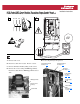
A. Remove front covers.
B. Disconnect cables from cassette. Remove cassette.
C. Remove the Plastic Shield by taking out the screws.
D. Remove the screws securing the HIM Support Plate.
Disconnect cables. Remove HIM Support Plate and set
aside.
E. Locate component(s) to be replaced.
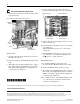
HIM Support Plate
Remove Screws
(6 Places)
Plastic Shield
Power Interface Board
See Steps H
-M
Current Transducers
See Steps H
-R
Thermistor
See Steps F
-G
Power Modules
See Steps
H-M & S-Z
Power Supply
Board
See Steps H
-I
SCRs & Brake
IGBT
See Steps a-m
on page 4
WIRE RANGE: 14-1/0 AWG (2.5-35 MM
2
)
TORQUE: 32 IN-LB (3.6 N-M)
STRIP LENGTH: 0.67 IN (17 MM)
USE 75 C CU WIRE ONLY
POWER TERMINAL RATINGS
WIRE RANGE: 6-1/0 AWG (16-35 MM
2
)
TORQUE: 44 IN-LB (5 N-M)
STRIP LENGTH: 0.83 IN (21 MM)
GROUND TERMINAL RATINGS (PE)
300 VDC EXT PWR SPLY TERM (PS+, PS-)
WIRE RANGE: 22-10 AWG (0.5-4 MM
2
)
TORQUE: 5.3 IN-LB (0.6 N-M)
STRIP LENGTH: 0.35 IN (9 MM)
17
21
INPUT ACOUTPUT
Optional
Communications
Module
9
2
DC–DC+
0V
0V