
User guide

Installation Instructions
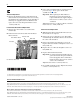
Optional
Communications
Module
L2L1T3T2T1 L3
INPUTOUTPUT
USE 75 C
COPPER WIRE
ONLY
TORQUE
52 IN-LB
(6 N-M)
BR2
PS+
PS–
BR1 DC+ DC–
USE 75 C COPPER WIRE ONLY, TORQUE 52 IN-LB (6 N-M)
22-10
AWG
5.3 IN-LB
(0.6 N-M)
WIRE STRIP
2
0V
0V
DC–DC+
3
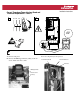
Current Transducer/Power Interface Board and
Thermistor Replacement - Frame 5
1
L1 L2 L3
O
I
=
A. Remove front panel.
B. Remove the HIM Support Plate by taking out the six
screws. Label and remove cables.
C. Locate component(s) to be replaced.
HIM Support Plate
Remove Screws
(6 Places)
Power Interface Board
Current Transducers
Thermistor