70 Enhanced Control and 700 Vector Control Reference Manual www.abpowerflex.
Important User Information Solid state equipment has operational characteristics differing from those of electromechanical equipment. Safety Guidelines for the Application, Installation and Maintenance of Solid State Controls (Publication SGI-1.1 available from your local Rockwell Automation sales office or online at www.rockwellautomation.com/literature) describes some important differences between solid state equipment and hard-wired electromechanical devices.
Table of Contents Preface Overview Manual Conventions . . . . . . . . . . . . . . . . . . . . . . . . . . . . . . . . . . . . . . . . . . . . . . . . . . . . . . . . . . . . . . .1 Reference Materials . . . . . . . . . . . . . . . . . . . . . . . . . . . . . . . . . . . . . . . . . . . . . . . . . . . . . . . . . . . . . . . .1 General Precautions . . . . . . . . . . . . . . . . . . . . . . . . . . . . . . . . . . . . . . . . . . . . . . . . . . . . . . . . . . . . . . . .
ii Table of Contents Speed Reference . . . . . . . . . . . . . . . . . . . . . . . . . . . . . . . . . . . . . . . . . . . . . . . . . . . . . . . . . . . . . . . . 98 Speed Regulation . . . . . . . . . . . . . . . . . . . . . . . . . . . . . . . . . . . . . . . . . . . . . . . . . . . . . . . . . . . . . . . 101 Speed/Torque Mode . . . . . . . . . . . . . . . . . . . . . . . . . . . . . . . . . . . . . . . . . . . . . . . . . . . . . . . . . . . . . 105 Start Permissives . . . . . . . . . . . . . . . . .
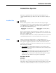
Preface Overview The purpose of this manual is to provide detailed drive information including operation, parameter descriptions and programming. Manual Conventions This manual covers the PowerFlex 70EC and the PowerFlex 700VC Drives. Some of the information presented applies to specific drives. The following symbols will be used throughout to identify specific drive information.
2 General Precautions General Precautions ! ! ! ! ATTENTION: This drive contains ESD (Electrostatic Discharge) sensitive parts and assemblies. Static control precautions are required when installing, testing, servicing or repairing this assembly. Component damage may result if ESD control procedures are not followed. If you are not familiar with static control procedures, reference A-B publication 8000-4.5.2, “Guarding Against Electrostatic Damage” or any other applicable ESD protection handbook.
Reference Information Detailed Drive Operation Accel/Decel Time 70EC 700VC 700H This chapter explains PowerFlex drive functions in detail. Explanations are organized alphabetically by topic. Refer to the Table of Contents for a listing of topics. [Accel Time 1, 2] [Decel Time 1, 2] ✔ ✔ The Accel Time parameters set the rate at which the drive ramps its output frequency after a Start or Stop command or during a change in command frequency (speed change).
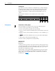
4 Analog Inputs Configuration Type 2 Alarms are always enabled (not configurable). Type 1 Alarms will always be displayed in [Drive Alarm 1], but can be configured to either mask or allow specific alarms from a) turning on the “Alarm” bit within the [Drive Status 1] parameter and b) turning on a digital output when [Digital Outx Sel] is set to “Alarm.” For each Alarm Config bit, 0 = alarm disabled and 1 = alarm enabled.
Analog Inputs 5 Example 1 − − − − − − [Anlg In Config], bit 0 = “0” (Voltage) [Speed Ref A Sel] = “Analog In 1” [Speed Ref A Hi] = 60 Hz [Speed Ref A Lo] = 0 Hz [Analog In 1 Hi] = 10V [Analog In 1 Lo] = 0V This is the default setting, where 0 volts represents 0 Hz and 10 volts represents 60 Hz providing 1024 steps (10 bit analog input resolution) between 0 and 60 Hz.
Analog Inputs Example 3 − − − − − − [Anlg In Config], bit 0 = “0” (Voltage) [Speed Ref A Sel] = “Analog In 1” [Speed Ref A Hi] = 30 Hz [Speed Ref A Lo] = 0 Hz [Analog In 1 Hi] = 10V [Analog In 1 Lo] = 0V This is an application that only requires 30 Hz as a maximum output frequency, but is still configured for full 10 volt input. The result is that the resolution of the input has been doubled, providing 1024 steps between 0 and 30 Hz.
Analog Inputs 7 Example 6 − − − − − − [Anlg In Config], bit 0 = “0” (Voltage) [Speed Ref A Sel] = “Analog In 1” [Speed Ref A Hi] = 60 Hz [Speed Ref A Lo] = 0 Hz [Analog In 1 Hi] = 5V [Analog In 1 Lo] = 0V This configuration is used when the input signal is 0-5 volts. Here, minimum input (0 Volts) represents 0 Hz and maximum input (5 Volts) represents 60 Hz. This allows full scale operation from a 0-5 volt source.
Analog Inputs Square Root The square root function can be applied to each analog input through the use of [Analog In Sq Root]. The function should be enabled if the input signal varies with the square of the quantity (e.g. drive speed) being controlled. If the mode of the input is bipolar voltage (–10v to 10v), then the square root function will return 0 for all negative voltages. The function uses the square root of the analog value as compared to its full scale (e.g. 5V = 0.5 or 50% and 0.5 = 0.
Analog Inputs [Analog In x Loss] 0, “Disabled” (default) 1, “Fault” 2, “Hold Input” 3, “Set Input Lo” 4, “Set Input Hi” 5, “Goto Preset1” 6, “Hold OutFreq” Normal Operation Disabled Faults Holds speed at last valid analog input level. Follows the maximum of [Minimum Speed] or [Speed Ref x Lo]. Follows the minimum of [Maximum Speed] or [Speed Ref x Hi]. Follows [Preset Speed 1]. Follows the last commanded output frequency.
Analog Outputs Analog Outputs 70EC 700VC 700H 10 ✔ ✔ Each drive has one or more analog outputs that can be used to annunciate a wide variety of drive operating conditions and values. The user selects the analog output source by setting [Analog Out Sel]. Configuration The analog outputs have 10 bits of resolution yielding 1024 steps. The analog output circuit has a maximum 1.3% gain error and a maximum 100 mV offset error. For a step from minimum to maximum value, the output will be within 0.
Analog Outputs 11 Example 2: Unsigned Output Quantity, Negative Slope − [Analog Out1 Sel] = “Output Current” − [Analog Out1 Lo] = 9 volts − [Analog Out1 Hi] = 1 volts 10V [Analog Out1 Lo] Analog Output Voltage [Analog Out1 Hi] 0V 0% 200% Output Current This example shows that [Analog Out1 Lo] can be greater than [Analog Out1 Hi]. The result is a negative slope on the scaling from original quantity to analog output voltage.
12 Analog Outputs Filtering Software filtering is performed on quantities that can be monitored as described in the following table. The purpose of this filtering is to provide a signal and display that is less sensitive to noise and ripple.
Auto/Manual 70EC 700VC 700H Auto/Manual ✔ ✔ 13 The purpose of the Auto/Manual function is to permit temporary override of speed control, or both speed control and start (run)/stop control. Each connected HIM or the control terminal block is capable of performing this function. However, only one device may own “Manual” control and must release the drive back to “Auto” control before another device can be granted “Manual” control.
14 Auto/Manual General Rules The following rules apply to the granting and releasing of Manual control: 1. Manual control is requested through a one-time request (Auto/Man toggle, not continuously asserted). Once granted, the terminal holds Manual control until the Auto/Man button is pressed again, which releases Manual control (e.g. back to Auto mode). 2. Manual control can be granted to a device only if another device does not presently own Manual control. 3.
Auto Restart 70EC 700VC 700H Auto Restart ✔ ✔ 15 The Auto Restart feature provides the ability for the drive to automatically perform a fault reset followed by a start attempt without user or application intervention. This allows remote or “unattended” operation. Only certain faults are allowed to be reset. Certain faults (Type 2) that indicate possible drive component malfunction are not resettable.
16 Autotune Aborting an Auto-Reset/Run Cycle During an auto reset/run cycle the following actions/conditions will abort the reset/ run attempt process. • Issuing a stop command from any source. (Note: Removal of a 2-wire run-fwd • • • • • • or run-rev command is considered a stop assertion). Issuing a fault reset command from any source. Removal of the enable input signal. Setting [Auto Rstrt Tries] to zero. A fault which is not auto resettable. Removing power from the drive.
Autotune 17 Autotune Procedure for Sensorless Vector and Economizer The purpose of Autotune is to identify the motor flux current and stator resistance for use in Sensorless Vector Control and Economizer modes.
18 Bus Regulation Refer to the "Autotune Procedure for Sensorless Vector and Economizer" on page 17 for a description of these tests. After the Static or Dynamic Autotune, the Inertia test should be performed. The motor shaft will rotate during the inertia test. During the inertia test the motor should be coupled to the load to find an accurate value. The inertia test can be performed during the Start-up routine on the LCD HIM.
Bus Regulation Single Seq 500 S/s 19 0V Fault @Vbus Max 3 Drive Output Shut Off 2 1 Ch1 100mV Ch3 500mV Ch2 100mV M 1.00s Ch3 1.47 V With bus regulation enabled, the drive can respond to the increasing voltage by advancing the output frequency until the regeneration is counteracted. This keeps the bus voltage at a regulated level below the trip point. DB Bus Motor Speed Output Frequency The bus voltage regulator takes precedence over acceleration/deceleration. See Figure 1.
Bus Regulation Figure 1 Bus Voltage Regulator, Current Limit and Frequency Ramp.
Bus Regulation 21 The derivative term senses a rapid rise in the bus voltage and activates the bus regulator prior to actually reaching the bus voltage regulation set point Vreg. The derivative term is important since it minimizes overshoot in the bus voltage when bus regulation begins thereby attempting to avoid an over-voltage fault. The integral channel acts as the acceleration or deceleration rate and is fed to the frequency ramp integrator.
Bus Regulation The bus voltage regulation setpoint is determined from bus memory (a means to average DC bus over a period of time). The following tables and figure describe the operation.
Copy Cat 23 If [Bus Reg Mode x] is set to “Both-DB 1st” Both regulators are enabled, and the operating point of the Dynamic Brake Regulator is lower than that of the Bus Voltage Regulator. The Bus Voltage Regulator setpoint follows the “DB Turn On” curve. The Dynamic Brake Regulator follows the “DB Turn On” and turn off curves.
Current Limit Current Limit 70EC 700VC 700H 24 ✔ ✔ There are 5 ways that the drive can protect itself from overcurrent or overload situations: • Hardware Overcurrent - This is a feature that instantly faults the drive if the output current exceeds this value. The value is fixed by hardware and is typically 250% of drive rated amps. The fault code for this feature is F12 “HW Overcurrent.” This feature cannot be defeated or mitigated.
Datalinks Programmable Controller I/O Image Table Remote I/O Communication Module 25 Adjustable Frequency AC Drive Output Image Block Transfer Logic Command Analog Reference WORD 3 WORD 4 WORD 5 WORD 6 WORD 7 Datalink A Parameter/Number Data In A1 Data In A2 300 301 Datalink A Data Out A1 310 Data Out A2 311 Input Image Block Transfer Logic Status Analog Feedback WORD 3 WORD 4 WORD 5 WORD 6 WORD 7 Rules for Using Datalinks • A Datalink consists of 4 words, 2 for Datalink x IN and 2 for Datalink x
26 DC Bus Voltage / Memory Datalink A1 A2 Most/Least Significant Word Parameter -Not Used0 MSW 242 Data (decimal) 0 13 Even if non-consecutive Datalinks are used (in the next example, Datalinks A1 and B2 would not be used), data is still returned in the same way.
Digital Inputs 27 • Run Forward, Run Reverse These settings cause the drive to run and with a specific direction, as long as the configured input is held closed. Also, these “2-wire” settings prevent any other connected device from starting the drive. To use a “2-wire” digital input setting that is compatible with start commands from a communication adapter, see "Run w/Comm" on page 28.
28 Digital Inputs Example 2 A drive is faulted and the “Run Level” input is held closed the entire time. Next, the network issues a “Stop/Clear Faults” command, or another digital input programmed for “Stop/Clear Faults” is activated, or the “Stop button is pressed on the HIM. The drive will not restart until the “Run Level” input is opened and then re-closed, because the fault clearing method used was combined with a stop command.
Digital Inputs 29 The drive will not jog while the drive is running or while the “Stop-Clear Faults” input is open. Start has precedence. ! ATTENTION: If a normal drive start command is received while the drive is jogging, the drive will switch from jog mode to run mode. The drive will not stop, but may change speed and/or change direction. Important: Direction control is an “Exclusive Ownership” function (see Owners). This means that only one control device (terminal block, DPI device, HIM, etc.
30 Digital Inputs • MOP Increment, MOP Decrement These functions are used to increment and decrement the Motor Operated Potentiometer (MOP) value inside the drive. The MOP is a reference value that can be incremented and decremented by external devices. The MOP value will be retained through a power cycle. In order for the drive to use the MOP value as the current speed reference, either [Speed Ref A Sel] or [Speed Ref B Sel] must be set to “MOP.” Refer to "MOP" on page 50.
Digital Inputs 31 • Local Control This input function allows exclusive control of all drive logic functions from the terminal block. If it is closed, the terminal block has exclusive control (disabling all the DPI devices) of drive logic, including start, reference selection, acceleration rate selection, etc. The exception is the stop condition, which can always be asserted from any connected control device.
32 Digital Inputs • Precharge Enable This function is used to manage disconnection from a common DC bus. If the input is closed, this indicates that the drive is connected to common DC bus and normal precharge handling can occur, and that the drive can run (start permissive).
Digital Outputs 33 • User Set Select 1 and 2 These settings are used in the “dynamic mode” of user sets, which provides switching between entire parameter sets from digital input combinations. See "User Sets" on page 114 for a complete description of these modes and the digital input combinations that activate each mode.
34 Digital Outputs Condition Economize Motor Overld Power Loss PI Enabled PI Hold Drive Overld Description The drive is currently reducing the output voltage to the motor to attempt to reduce energy costs during a lightly loaded situation. The drive output current has exceeded the programmed [Motor NP FLA] and the electronic motor overload function is accumulating towards an eventual trip.
Digital Outputs 35 Level] is degrees C. No units will be displayed on HIMs, offline tools, devices communicating over a network, PLC’s, etc. The minimum and maximum value for [Dig Outx Level] is independent of the selection for [Dig Outx Sel].
36 Direction Control 4. Controlled by the Network This configuration is used when it is desired to control the digital outputs over network communications instead of a drive related function. In this case, [Digital Out x Sel] is set to “Param Cntl,” in which case the bit value of [DigOut Setpt], parameter 379 energizes the respective digital output. Bit 0 corresponds to output 1. Bit 1 corresponds to output 2, and so on.
DPI 70EC 700VC 700H DPI ✔ ✔ 37 Drive Peripheral Interface (DPI) is a CAN based, Master-Slave protocol, created to provide a standard way of connecting motor control products and optional peripheral devices together. It allows multiple (up to 6) devices to communicate with a motor control product without requiring configuration of the peripheral. DPI provides two basic message types called Client/Server (C/S) and Producer/ Consumer (P/C).
38 DPI Peer-to-Peer operation Peer-to-Peer messaging allows two devices to communicate directly rather than through the master or host (e.g. drive). They are the same priority as C/S messages and will occur in the background. If an LCD HIM is attached, it will be able to directly access peripheral parameters (e.g. communication adapter parameters) using Peer-to-Peer messages. Peripheral devices will be scanned at a 10ms rate.
DriveGuard 70EC 700VC 700H DriveGuard 39 Refer to “DriveGuard Safe-Off User Manual” publication PFLEX-UM001. Drive Overload 70EC 700VC 700H ✔ ✔ ✔ The drive overload function has two separate protection schemes, an inverse time protection based on current, and thermal manager based on measured power module temperature and operating conditions. The drive may fold back current limit when either of these methods detects a problem.
Drive Overload Current Level Figure 2 Normal Duty Boundary of Operation 1.80 1.70 1.60 1.50 1.40 1.30 1.20 1.10 1.00 0.90 0.80 0.70 0.60 0.50 0.40 0.30 0.20 0.10 0.00 1.00 10.00 100.00 1,000.00 Time (Seconds) Heavy Duty operation follows the same algorithm as Normal Duty, but allows a larger percentage of rated current (one size smaller motor). The percentages are 150% for 60 seconds, 200% for 3 seconds and 220% for 100 milliseconds (see "Normal Duty and Heavy Duty Operation" on page 39.
Drive Overload 41 Figure 4 Thermal Manager Inputs/Outputs DTO Select (Off,PWM,ILmt,Both) DTO Fault (On,Off) PWM Frequency (2 - 12 kHz) Active PWM Frequency (2 - 12 kHz) Current Limit (0 - 200%) Active Current Limit (0 - 200%) Temperature Analog Input (Volts) I_total (Amps) V_dc (Volts) Output Frequency Drive Thermal Overload Drive Temperature (x deg C) IGBT Temperature (x deg C) KHz Alarm (On, Off) ILmt Alarm (On, Off) Power Board Data The following is a generalization of the calculations don
42 Droop Low Speed Operation When operation is below 4 Hz, the IGBT duty cycle is such that heat will build up rapidly in the device. The thermal manager will increase the calculated IGBT temperature at low output frequencies and will cause corrective action to take place sooner. When the drive is in current limit the output frequency is reduced to try to reduce the load.
Faults 70EC 700VC 700H Faults ✔ ✔ 43 Faults are conditions occurring within and/or outside of the drive. These conditions are (by default) considered to be important enough that drive operation is discontinued. Faults are annunciated via the HIM, communications and/or digital outputs. Once a fault occurs, it is latched, requiring a fault reset action. If the condition that caused fault still exists when the fault is reset, the drive will fault again and the fault will be latched again.
44 Faults Fault Code/Text [Fault Code x] The fault code for each entry can be read in its respective read-only parameter. When viewed with a HIM, only the fault code (not text) is displayed. If viewed via a DPI peripheral (communications network), the queue is not accessed through parameters, and a text string of up to 16 characters is also available.
Flux Braking 45 Following is a brief list of each configurable fault. Some of these faults are explained in more detail in their own section of this document.
Flux Up The first method is during a normal start. Flux is established as the output voltage and frequency are applied to the motor. While the flux is being established, the unpredictable nature of the developed torque may cause the rotor to oscillate even though acceleration of the load may occur. In the motor, the acceleration profile may not follow the commanded acceleration profile due to the lack of developed torque.
Flying Start 70EC 700VC 700H Flying Start ✔ ✔ 47 The Flying Start feature is used to start into a rotating motor, as quick as possible, and resume normal operation with a minimal impact on load or speed. When a drive is started in its normal mode it initially applies a frequency of 0 Hz and ramps to the desired frequency. If the drive is started in this mode with the motor already spinning, large currents will be generated.
High Resolution Speed Reference High Resolution Speed Reference 70EC 700VC 700H 48 ✔ The high resolution speed reference provides a 32 bit (as opposed to a 16 bit) speed reference from a communication network. The high resolution 32 bit reference is scaled so that a value of 2147483647 corresponds to [Maximum Freq], parameter 55 if [DPI Ref Select], parameter 298 = “0, Max Freq,” or 2147483647 corresponds to [Maximum Speed], parameter 82 if [DPI Ref Select] = “1, Max Speed.
Language 70EC 700VC 700H Language ✔ ✔ 49 Seven languages are supported; English, Spanish, German, Italian, French, Portuguese and Dutch. All drive functions and information displayed on an LCD HIM are shown in the selected language. The desired language can be selected by any of the following methods. • On initial drive power-up, a language choice screen appears. • The language choice screen can also be recalled at any time to change to a new Load Loss Detection 70EC 700VC 700H language.
MOP MOP 70EC 700VC 700H 50 ✔ ✔ The Motor Operated Pot (MOP) function uses either digital inputs or network commands to increment or decrement the speed reference at a programmed rate. The MOP has three components: • [MOP Rate] parameter • [Save MOP Ref] parameter • [MOP Frequency] parameter MOP increment input MOP decrement input The MOP rate is the rate at which the MOP reference will change when commanded to increment or decrement. This rate is independent of acceleration and deceleration times.
Motor Control Modes 70EC 700VC 700H Motor Control Modes 51 [Motor Cntl Sel] selects the output mode of the drive. The choices are: • Custom Volts/Hertz ✔ ✔ • • • • • Used in multi-motor or synchronous motor applications. Fan/Pump Volts/Hertz Used for centrifugal fan/pump (variable torque) applications to achieve maximum energy savings. Sensorless Vector Used for most constant torque applications. Provides excellent starting, acceleration and running torque.
52 Motor Control Modes 2. Custom Custom Volts/Hertz allows a wide variety of patterns. The default configuration is a straight line from zero to rated voltage and frequency.
Motor Control Modes 53 In sensorless vector control, the drive commands a specific amount of voltage to develop flux. Maximum Voltage Base Voltage (Nameplate) urve ad C te ima prox App Lo Full Ir Voltage te ima prox App urve ad C Lo No Base Frequency (Nameplate) Maximum Frequency Sensorless Vector w/Economizer Economizer mode consists of the sensorless vector control with an additional energy savings function.
54 Motor Nameplate Data Figure 8 Flux Vector High Bandwidth Current Regulator CURRENT FEEDBACK Flux Reg. SPEED REF. Speed Reg. V mag Current Reg. TORQUE REF. Voltage Control Inverter Motor V ang Encoder Adaptive Controller SLIP AUTOTUNE PARAMETERS Motor Nameplate Data 70EC 700VC 700H SPEED FEEDBACK ✔ ✔ These parameters provide motor information to the drive, so the drive can both protect the motor and also make internal adjustments to provide the best performance.
Motor Overload Curve 100000 Trip Time (Seconds) ✔ ✔ 55 The motor overload protection feature uses an IT (inverse time) algorithm to model the temperature of the motor and follows the same curve as a physical class 10 overload device. 10000 Cold Hot 1000 100 10 100 125 150 175 200 Full Load Amps (%) 225 250 [Motor NP FLA] is used by the overload feature to establish the 100% level (y axis) shown in the graph above.
Motor Overload 3. [Motor OL Hertz] is used to further protect motors with limited speed ranges. Since many motors do not have sufficient cooling ability at lower speeds, the overload feature can be programmed to increase protection in the lower speed areas. This parameter defines the frequency where derating the motor overload capacity should begin. For all settings of overload Hz other than zero, the overload capacity is reduced to 70% when output frequency is zero.
Notch Filter 57 Notch Filter 70EC 700VC 700H Important: If the application requires high overload current for long durations (e.g. 150% for 60 seconds), heavy duty sizing (between drive and motor) will be required. See "Normal Duty and Heavy Duty Operation" on page 39. ✔ A notch filter exists in the torque reference loop to reduce mechanical resonance created by a gear train. [Notch Filter Freq] sets the center frequency for the 2 pole notch filter, and [Notch Filter K] sets the gain.
58 Notch Filter Figure 11 Resonance Figure 12 represents the same mechanical gear train but with [Notch Filter Freq] set to 10.
Owners 70EC 700VC 700H Owners ✔ ✔ 59 Owners are status parameters that show which peripheral devices (HIMs, comm ports, etc.) are commanding or have exclusive control of specific control functions. The list of devices also includes the drive’s control terminal block. Exclusive Only one device at a time can control the drive and only one owner bit will be high.
Password Password 70EC 700VC 700H 60 By default the password is set to 00000 (password protection disabled). ✔ ✔ Logging in to the Drive Step Key(s) 1. Press the Up or Down Arrow to enter your password. Press Sel to move from digit to digit. Example Displays Login: Enter Password 9999 2. Press Enter to log in. Logging Out Step Key(s) You are automatically logged out when the User Display appears. If you want to log out before that, select “log out” from the Main Menu.
Position Indexer/ Speed Profiler 70EC 700VC 700H Position Indexer/Speed Profiler ✔ 61 Overview The profile/indexer may be configured as a velocity regulator or a position regulator. If position control is desired, encoder feedback is required. Parameter 088, [Speed/Torque Mod] is used to select the “Pos/Spd Prof” mode. Sixteen steps are available with this feature. Common Guidelines for all step types Direction Control - The drive must be configured to allow the profile to control the direction.
62 Position Indexer/Speed Profiler Profile Command Control Word The profile/indexer is controlled with [Profile Command], parameter 705. The bit definitions are as follows: Bit 0 1 2 3 4 5-7 8 Name Start Step 0 Start Step 1 Start Step 2 Start Step 3 Start Step 4 Reserved Hold Step Description The binary value of these bits determines which step will be the starting step for the profile when a start command is issued.
Position Indexer/Speed Profiler 63 Position Regulated Step Parameters Each of the Position Regulated steps has the following associated parameters or functions: Step Type Encoder Absolute Value Position & Direction Velocity Speed Accel Time Accel Rate Decel Time Decel Rate Next Step Condition At Position = 1 Dwell Dwell Time Batch X Next Next Step Encoder Incremental Position & Direction Speed Accel Rate Decel Rate At Position =1 Dwell Time Batch Number Next Step End Hold Position X X X X At Position =1
Position Indexer/Speed Profiler Homing to Limit Switch with Encoder Feedback - When “Find Home” is commanded, the homing routine is run when a start command is issued. The Homing bit (11) in [Profile Status], parameter 700 will be set while the homing routine is running. The drive will ramp to the speed and direction set in [Find Home Speed], parameter 713 at the rate set in [Find Home Ramp], parameter 714 until the digital input defined as Home Limit is activated.
Position Indexer/Speed Profiler 65 Disable Homing Requirement – If a home position is not required, the routine can be disabled by clearing [Alarm Config 1] bit 17 “Prof SetHome” to “0.” This will disable the alarm from being set when “Pos/Spd Prof” mode is configured in [Speed/Torque Mod] and will set the present position as home. Once Homing is complete the “Find Home” command must be removed to allow the profile to be run.
Position Indexer/Speed Profiler Time Blend - When started the drive will ramp to the desired velocity and hold speed for the programmed time at which point it will transition to the next step and ramp to the programmed velocity without going to zero speed. The example below shows a five step profile. The first three are Time Blend steps followed by an Encoder Abs step to zero then an End step.
Position Indexer/Speed Profiler 67 Digital Inputs 50 Encoder Speed 45 250 40 150 35 Digital Input #6 Units Traveled Profile Status (Scaled) 350 30 50 0 25 30 10 50 70 90 110 130 150 170 -50 20 Digital Input #5 5s Dwell 10 Digital Input #4 Step 6 -250 Digital Input #3 Step 1 Step 2 Step 5 Step 4 Step 3 5 0 -350 Time [Encoder Speed], 415 Step # 1 2 3 4 5 6 Current Step 15 -150 [Profile Status], 700 Step X Type Digital Input Digital Input Digital Input Digital Input Param Le
Position Indexer/Speed Profiler Step # 1 2 3 4 5 Step X Type EncInc Blend EncInc Blend EncInc Blend Encoder Abs End Step X Velocity 100 200 300 400 N/A Step X AccelTime 0.5 0.5 0.5 0.5 N/A Step X DecelTime 0.5 0.5 0.5 0.5 0.5 Step X Value 10.00 10.00 10.00 0.00 N/A Step X Dwell 0.00 0.00 0.00 1.00 0.00 Step X Batch 1 1 1 1 N/A Step X Next 2 3 4 5 N/A Encoder Incremental Blend with Hold - This profile is the same as the previous, but contains the Hold function.
Position Indexer/Speed Profiler 69 Encoder Incremental Blend w/Velocity Override 350 30 Profile Status 25 150 20 Velocity Override 50 -50 10 20 30 40 50 60 70 80 90 100 110 15 -150 10 -250 Step 4 Step 3 -350 Step 1 Step 5 5 Step 2 -450 Current Step Encoder Speed Complete Units Traveled 250 0 Time [Encoder Speed], 415 Step # 1 2 3 4 5 Step X Type EncInc Blend EncInc Blend EncInc Blend Encoder Abs End [Profile Status], 700 Step X Velocity 100 200 300 400 N/A [Units Travele
Position Indexer/Speed Profiler Parameter Level Step 3 Dwell Level, 745 30 250 25 150 Step 2 Dwell Level, 735 20 50 -50 8 13 18 23 28 33 38 43 48 53 58 Units Traveled Profile Status (Scaled) 350 Encoder Speed 70 15 -150 10 Step 1 Dwell Level, 725 Step 4 Step 5 5 -350 Step 1 Step 2 Step 3 Current Step -250 0 -450 Time [Encoder Speed], 415 Step # 1 2 3 4 5 Step X Type Param Level Param Level Param Level Encoder Abs End [Profile Status], 700 Step X Velocity 100 200 300 400 N
Position Indexer/Speed Profiler 71 Encoder Incremental w/Dwell 350 30 25 Profile Status 150 Complete 20 50 -50 70 90 110 130 150 170 190 210 15 At Position -150 10 -250 Step 5 5 Step 4 -350 Step 2 Step 1 Current Step Encoder Speed Units Traveled 250 Step 3 0 -450 Time [Encoder Speed], 415 Step # 1 2 3 4 5 Step X Type Encoder Incr Encoder Incr Encoder Incr Encoder Abs End [Profile Status], 700 Step X Velocity 100 200 300 400 N/A [Units Traveled], 701 Step X AccelTime 0.5 0.
Position Indexer/Speed Profiler Encoder Incremental with Velocity Override - This profile is the same as Encoder Incr, but contains the “Velocity Override” function. During step 3 the “Vel Override” bit was set. While active the [Step 3 Velocity] is multiplied by [Vel Override]. In this example [Vel Override] is 150% causing the speed to be 450rpm rather than 300.
Power Loss 70EC 700VC 700H Power Loss ✔ ✔ 73 The drive contains a sophisticated algorithm to manage initial application of power as well as recovery from a partial power loss event. The drive also has programmable features that can minimize the problems associated with a loss of power in certain applications. Terms The following terms are used internally by the drive and are defined below for a complete understanding of power loss functionality.
74 Power Loss Line Loss Mode = Decel 700 Recover Close Trigger Open 650 600 DC Bus Volts DC Bus Volts 650 Line Loss Mode = Coast 700 550 600 550 500 500 450 450 400 Recover Close Trigger Open 400 350 400 AC Input Volts 450 350 400 AC Input Volts 450 Table F PF700VC Bus Levels Class Vslew Vrecover Vclose Vtrigger1,2 Vtrigger1,3 Vopen Vopen4 Vmin Voff 5 200/240V AC 1.2V DC Vmem – 30V Vmem – 60V Vmem – 60V Vmem – 90V Vmem – 90V 153V DC 153V DC – 400/480V AC 2.
Power Loss 75 Power Loss Actions The drive is designed to operate at a nominal input voltage. When voltage falls below this nominal value by a significant amount, action can be taken to preserve the bus energy and keep the drive logic alive as long as possible. The drive has three methods of dealing with low bus voltages: • “Coast” - Disable the drive and allow the motor to coast.
76 Power Loss Decel This mode of operation is useful if the mechanical load is high inertia and low friction. By recapturing the mechanical energy, converting it to electrical energy and returning it to the drive, the bus voltage is maintained. As long as there is mechanical energy, the ride through time is extended and the motor remains fully fluxed. If AC input power is restored, the drive can ramp the motor to the correct speed without the need for reconnecting.
Process PID Loop 77 680V 620V 560V Bus Voltage 365V 305V Motor Speed Power Loss Output Enable Pre-Charge Drive Fault 480V example shown, see Table F for further information. Coast Input and Decel Input 700VC ONLY Process PID Loop 70EC 700VC 700H These modes operate similarly to their “non-input” versions, but provide additional ride through time. This is accomplished by early sensing of the power loss via an external device that monitors the power line.
78 Process PID Loop 0 Volts Equilibrium Point [PI Reference Sel] Dancer Pot [PI Feedback Sel] 10 Volts Master Speed Reference When the PID is disabled the commanded speed is the ramped speed reference. Slip Comp + Slip Adder + Spd Ref PI Ref PI Fbk Open Loop Linear Ramp & S-Curve Spd Cmd + + Process PI Controller Process PI Speed Control PI Disabled When the PID is enabled, the output of the PID Controller is added to the ramped speed reference.
Process PID Loop Pump Pressure Transducer Motor PI Feedback 79 Desired Pressure [PI Reference Sel] However, when additional valves in the system are opened and the pressure in the system drops, the PID error will alter its output frequency to bring the process back into control. When the PID is disabled the commanded speed is the ramped speed reference.
80 Process PID Loop PID Configuration [PI Configuration] is a set of bits that select various modes of operation. The value of this parameter can only be changed while the drive is stopped. • Exclusive Mode - see page 78. • Invert Error - This feature changes the “sign” of the error, creating a decrease in output for increasing error and an increase in output for decreasing error. An example of this might be an HVAC system with thermostat control.
Process PID Loop 81 PI Enabled Start at Spd Cmd PI Output Spd Cmd Pre-load to Command Speed When the PID is configured to have exclusive control of the commanded speed and the drive is in current limit or voltage limit the integrator is preset to the commanded speed so that it knows where to resume when no longer in limit. • Ramp Ref - The PID Ramp Reference feature is used to provide a smooth transition when the PID is enabled and the PID output is used as a speed trim (not exclusive control).
Process PID Loop • Stop Mode - When Stop Mode is set to “1” and a Stop command is issued to the drive, the PID loop will continue to operate during the decel ramp until the PID output becomes more than the master reference. When set to “0,” the drive will disable PID and perform a normal stop. This bit is active in Trim mode only. 100.0 Normalized SQRT(Feedback) 82 75.0 50.0 25.0 0.0 -25.0 -50.0 -75.0 -100.0 -100.0 -75.0 -50.0 -25.0 0.0 25.0 50.0 75.0 100.
Process PID Loop 83 When a digital input is configured as “PI Enable,” the PID Enable bit of [PI Control] must be turned On for the PID loop to become enabled. If a digital input is not configured as “PI Enable” and the PID Enable bit in [PI Control] is turned On, then the PID loop may become enabled. If the PID Enable bit of [PI Control] is left continuously, then the PID may become enabled as soon as the drive goes into Run. If analog input signal loss is detected, the PID loop is disabled.
84 Process PID Loop PID Status [PI Status] parameter is a set of bits that indicate the status of the process PID controller • Enabled - The loop is active and controlling the drive output. • Hold - A signal has been issued and the integrator is being held at its current value. • Reset - A signal has been issued and the integrator is being held at zero. • In Limit - The loop output is being clamped at the value set in [PI Upper/Lower Limit].
Process PID Loop 85 Using Scale Blocks with PID Reference and Feedback Scale Blocks are included in the Reference and Feedback selections of the Process PID controller. This selects the output of the scale block for use as Reference or Feedback to the Process PID. PID Setpoint This parameter can be used as an internal value for the setpoint or reference for the process. If [PI Reference Sel] points to this parameter, the value entered here will become the equilibrium point for the process.
86 PTC Motor Thermistor Input PID Lower and Upper Limits/ Output Scaling The output value produced by the PID is displayed as ±100% in [PI Output Meter]. [PI Lower Limit] and [PI Upper Limit] are set as a percentage. In exclusive or speed trim mode, they scale the PID Output to a percentage of [Maximum Freq]. In torque trim mode, they scale the PID Output as a percentage of rated motor torque. Example Set the PID lower and Upper limits to ±10% with Maximum Frequency set to 100 Hz.
PWM Frequency 87 Fault Operation A fault will occur when the PTC resistance increases above 3230 ohms (5V DC), and must be cleared (reset) by a fault clear command (see "Faults" on page 43) after the resistance has decreased below 3230 ohms (5V DC). PWM Frequency 70EC 700VC 700H The drive will also fault if the PTC voltage drops below 0.2V DC, indicating a shorted PTC. ✔ ✔ In general, it is best to use the lowest possible PWM (switching) frequency that is acceptable for the application.
Regen Power Limit Regen Power Limit 70EC 700VC 700H 88 ✔ ✔ The [Regen Power Lim] is programmed as a percentage of the rated power. The mechanical energy that is transformed into electrical power during a deceleration or overhauling load condition is clamped at this level. Without the proper limit, a bus overvoltage may occur. Reset Parameters 70EC 700VC 700H When using the bus regulator [Regen Power Lim] can be left at factory default, – 50%.
Example with No S Curve 80.0 60.0 40.0 Hz 20.0 0.0 -20.0 -40.0 -60.0 -80.0 0.0 1.0 2.0 3.0 4.0 5.0 6.0 7.0 8.0 Seconds When S Curve is enabled, it adds time to the overall acceleration by a percentage of the programmed acceleration time. This is shown in the curves below, which represent 0%, 25%, 50% and 100% S Curve. Note that half of the “S” is added to beginning and half is added to the end of the ramp. 70.0 60.0 50.
S Curve Time to Accelerate When accelerating from 0 to maximum speed, with maximum speed set to 60 Hz, Ta = 2.0 sec, and S Curve = 25%, acceleration time is extended by 0.5 seconds (2.0 x 25%). When accelerating to only 30 Hz the amount of jerk control (S Curve) is the same, but the extended amount of acceleration time is different. 70.0 60.0 Hz 50.0 40.0 30.0 20.0 10.0 0.0 0.0 0.5 1.0 1.5 Seconds 2.0 2.5 3.
Safe-Off 70EC 700VC 700H Safe-Off 91 Refer to “DriveGuard Safe-Off User Manual” publication PFLEX-UM001. ✔ See also "Analog Scaling" on page 4 and page 10. Scale blocks are used to scale a parameter value. [ScaleX In Value] is linked to the parameter that you wish to scale. [ScaleX In Hi] and [ScaleX In Lo] determine the high and low values for the input to the scale block. [ScaleX Out Hi] and [ScaleX Out Lo] determine the corresponding high and low values for the output of the scale block.
92 Security Parameter Settings Parameter [Scale 1 In Hi] [Scale 1 In Lo] [PI Reference Sel] Value 2.5 V –2.5V 25, Scale Block1 Out [PI Reference Hi] 100 % [PI Reference Lo] –100 % Description 2.5 V = 200% torque from other drive –2.
Security 93 Any changes to [Write Mask Cfg] will not take effect until one of the following three events occur: • Power is removed and reapplied. • A drive reset (not reset to defaults) is performed. • [Write Mask Act], parameter 597, bit 15 transitions from “1” to “0.” The status of a port’s write access may be verified at [Write Mask Act]. For example, to verify that write access was disabled on “DPI Port 1”, bit 1 should equal bit 1 in [Write Mask Cfg].
Shear Pin Shear Pin 70EC 700VC 700H 94 ✔ ✔ As a default, the drive will fold back when the output current exceeds the current limit level. However, the shear pin feature can be used to instantly fault the drive when output current exceeds a programmed amount. Additionally, the drive can be programmed to ignore this condition during acceleration and deceleration which often requires current that would otherwise cause a shear pin fault.
Skip Frequency 95 Some machines may have a resonant operating frequency (vibration speed) that is undesirable or could cause equipment damage. To guard against continuous operation at one or more resonant points, parameters 084-086, ([Skip Frequency 1-3]) can be programmed. The value programmed into a skip frequency parameter, sets the center point for an entire “skip band” of frequencies. The width of the band (range of frequency around the center point) is determined by [Skip Freq Band], parameter 87.
Sleep Mode Sleep Mode 70EC 700VC 700H 96 ✔ ✔ The purpose of the Sleep-Wake function is to Start (wake) the drive when an analog signal is greater than or equal to the specified [Wake Level], and Stop (sleep) the drive when an analog signal is less than or equal to the specified [Sleep Level]. Setting [Sleep-Wake Mode] to “Direct” enables the sleep-wake function to work as described.
Sleep Mode 97 Table G Conditions Required to Start Drive (1)(2)(3) Input After Power-Up Stop Stop Closed Wake Signal Enable Enable Closed Wake Signal (4) Run Run Closed Run For. Wake Signal Run Rev. After a Drive Fault Reset by Stop-CF, HIM or TB Stop Closed Wake Signal New Start or Run Cmd.(4) Enable Closed Wake Signal New Start or Run Cmd.(4) New Run Cmd.(5) Wake Signal After a Stop Command Reset by Clear HIM or TB Faults (TB) Stop Closed Stop Closed Wake Signal Analog Sig.
98 Speed Reference When a device is commanding “local” control, the port that is commanding it has exclusive start control (in addition to ref select), essentially overriding the Sleep/ Wake function, and allowing the drive to run in the presence of a sleep situation. This holds true even for the case of Port 0, where a digital input start or run will be able to override a sleep situation.
Speed Reference 99 Network Reference When a network (communication adapter) is selected as the speed reference, a 16 bit word is used as the speed reference. If [Direction Mode], parameter 190 is set to “Bipolar”, the most significant bit (MSB) is used for direction control. Otherwise, the MSB is ignored. The remaining 15 bits (32767 decimal) provide the magnitude. By default, the maximum network value is scaled to [Maximum Freq], parameter 55.
100 Speed Reference Figure 17 Trim Trim Enable Select A Trim B Both None Reference A Reference B + + Trimmed Reference A + + Trimmed Reference B The source of the trim signal is selected through [Trim In Sel], parameter 117. All selections for [Speed Ref A] and [Speed Ref B] are also valid choices for a trim source. In addition, [Trim % Setpoint], parameter 116 is also available as a trim source.
Speed Regulation 101 Min/Max Speed Maximum and minimum speed limits are applied to the reference. These limits apply to the positive and negative references. The minimum speed limits will create a band that the drive will not run continuously within, but will ramp through. This is due to the positive and negative minimum speeds. If the reference is positive and less than the positive minimum, it is set to the positive minimum.
Speed Regulation Figure 18 Rotor Speed with/without Slip Compensation Open Loop Mode Slip Compensation Active Rotor Speed Load Applied Load Applied No Load 1.5 p.u. Load 1.0 p.u. Load 0.5 p.u. Load 0.5 p.u. Load 1.0 p.u. Load 1.5 p.u. Load Slip Compensation Active Load Removed Slip @ F.L.A. 0 0 Time Internally, the drive converts the rated slip in RPM to rated slip in frequency. To more accurately determine the rated slip frequency in hertz, an estimate of flux current is necessary.
Speed Regulation 103 Application Example - Baking Line The diagram below shows a typical application for the Slip Compensation feature. The PLC controls the frequency reference for all four of the drives. Drive #1 and Drive #3 control the speed of the belt conveyor. Slip compensation will be used to maintain the RPM independent of load changes caused by the cutter or dough feed. By maintaining the required RPM, the baking time remains constant and therefore the end product is consistent.
104 Speed Regulation Integral Gain The integral gain block outputs a torque command relative to the error integrated over a period of time. [Ki Speed Loop] sets the integral gain of the speed regulator. Its value is automatically calculated based on the bandwidth setting in [Speed Desired BW]. Integral gain may be manually adjusted by setting [Speed Desired BW] to a value of zero. Units are (per unit torque/sec) / (per unit speed).
Speed/Torque Mode 105 Speed Feedback Filter 700VC ONLY [Fdbk Filter Select] determines the type of filter to use for the speed feedback. The filter is used to filter out high frequency signals (noise) by reducing the gain at high frequencies. The selections for the filter are: Description No filter Select this value . . . 0 To select this type of filter . . .
106 Speed/Torque Mode The Min mode is typically used with positive torque and forward speed operation, the minimum of the two being closest to zero. The Max mode is opposite, typically used with reverse speed and negative torque, the maximum being the least negative (closest to zero). Sum mode is selected when set to “5.” This mode allows an external torque command to be added to the speed regulator output.
Speed/Torque Mode 107 When the Process PID loop is setup for torque trim ([Process PI Config], bit 8 “Torque Trim” is set to 1), the output of the Process PI Loop also becomes a torque reference. The final torque reference, in the Torque Mode, is the sum of scaled Torque Ref A, scaled Torque Ref B (700VC only) and the output of the Process PID loop when it is set to trim torque. Min Torq/Spd and Max Torq/Spd Modes These modes compare the speed and torque commands.
108 Start Permissives Absolute Min Mode 700VC ONLY This mode regulates to the smallest absolute value of torque or speed, when the torque reference and torque generated from the speed regulator are compared. Position/Speed Profile Mode 700VC ONLY Start Permissives 70EC 700VC 700H The drive operates as a speed or position regulator as determined by the Profile Step parameters (720-877) and Setup parameters (705-719).
Stop Modes 70EC 700VC 700H Stop Modes ✔ ✔ 109 Several methods are available for braking or stopping a load as described in the table below. Method Use When Application Requires . . . Ramp • The fastest stopping time or fastest ramp time for speed changes (external brake resistor or regenerative capability required for ramp times faster than the methods below). • High duty cycles, frequent stops or speed changes. (The other methods may result in excessive motor heating).
110 Stop Modes Detailed operation Mode Coast to Stop Description Bus Voltage Output Voltage Output Current Motor Speed Command Speed Time Stop Command Coast Time is load dependent Coast is selected by setting [Stop Mode A/B] to a value of “0.” When in Coast to Stop, the drive acknowledges the Stop command by shutting off the drive output and releasing control of the motor. The load and motor will coast until the kinetic energy is dissipated.
Stop Modes Mode Ramp 111 Description Bus Voltage Output Voltage Output Current Motor Speed Output Current Command Speed Output Voltage DC Brake Level Time Stop Command Zero Command Speed DC Brake Time This method uses drive output reduction to stop the load. Ramp is selected by setting [Stop Mode A/B] to a value of “1”. The drive will ramp the frequency to zero based on the deceleration time programmed into [Decel Time 1/2]. The “normal” mode of machine operation can utilize [Decel Time 1].
112 Stop Modes Mode Fast Brake Description Bus Voltage Output Voltage Output Current Motor Speed Command Speed Time Stop Command This method takes advantage of the characteristic of the induction motor whereby frequencies greater than zero (DC braking) can be applied to a spinning motor that will provide more braking torque without causing the drive to regenerate. 1. On Stop, the drive output will decrease based on the motor speed, keeping the motor out of the regen region.
User Display 113 Implementation Block Diagram for Fast Braking Current Regulator 0 IqCmd + Vq PI Va − Brake Level IdCmd T (θ) + Vb Vd PI Vc − IqFdbk θe IdFdbk 1/s Bus Voltage Reference + Gain fe PI − Frequency User Display 70EC 700VC 700H Bus Voltage ✔ ✔ The User Display is shown when module keys have been inactive for a predetermined amount of time. The display can be programmed to show pertinent information. Setting the User Display Step Key(s) 1.
User Sets User Sets 70EC 700VC 700H 114 ✔ ✔ Normal Mode The drive has additional parameter storage memory beyond what is being used for operation at any given time. This additional memory is divided up into 3 areas called User Sets. When the drive is stopped, a HIM command or parameter command (similar to Reset to Defaults) can be used to load any of these user sets.
Voltage Class 115 These parameter bits are normally written to over a network (using Datalinks) and control the user sets as follows: [Dyn UserSet Sel] Parameter 205, bit 1 0 0 1 1 [Dyn UserSet Sel] Parameter 205, bit 0 0 1 0 1 User Set 1 2 3 3 • [Dyn UserSet Actv], parameter 206 reports the status of Dynamic Mode and which User Set is active.
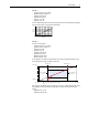
Voltage Tolerance Drive Rating 200-240 380-480 500-600 Nominal Line Voltage 200 208 240 380 400 480 600 600 690 Drive Full Power Range = Drive Operating Range = Nominal Motor Voltage 200* 208 230 380* 400 460 575* 575* 690 Drive Full Power Range 200-264 208-264 230-264 380-528 400-528 460-528 575-660 575-660 690-759 Drive Operating Range 180-264 342-528 432-660 475-759 475-759 Nominal Motor Voltage to Drive Rated Voltage +10%. Rated power is available across the entire Drive Full Power Range.
Appendix ✔ ✔ ATTENTION: To guard against unstable or unpredictable operation, the following parameters must only be changed by qualified service personnel. ! UTILITY 1500 ✔ ✔ Current Limit Integral gain. This gain is applied to the Min/Max: 0/10000 current limit error signal to eliminate steady state Units: 1 current limit error. A larger value increases overshoot during a step of motor current/load. Default: 500 501 [KD Current Limit] ✔ ✔ Current Limit Derivative gain.
3250 Diag-Motor Cntl The Stability Filter coefficient is used to adjust the Min/Max: 0/32767 bandwidth of a low pass filter. The smaller the value Units: 1 of this coefficient, the lower the bandwidth of the filter. Default: 64 509 [Lo Freq Reg KpId] This proportional gain adjusts the output voltage at very low frequency in response to the reactive, or d-axis, motor current. A larger value increases the output voltage change.
Integral gain for the slip frequency regulator. ✔ ✔ ✔ ✔ Min/Max: 0/1 Units: 1 Default: 64 ✔ ✔ Min/Max: 0/32767 Units: 1 Default: 32 ✔ ✔ Min/Max: 0/32767 Units: 1 Default: 100 ✔ ✔ Min/Max: 0/32767 Units: 1 Default: 500 ✔ ✔ Min/Max: 0/32767 Units: 1 Default: 1000 ✔ ✔ The delay that is enforced after a stop event prior to a Min/Max: 1/30000 flying start event. A setting of 1000 = 0.5 seconds. Units: 1 Default: 450 539 Freq Reg Kp ✔ ✔ Enables or disables the flux regulator.
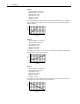
Diag-Vector Cntl UTILITY Gain adjustment for Flux Braking mode. 550 Ki Flying Start Integral gaing for Flying Start mode. 551 Ki DC Brake Integral gain for DC Braking mode. ✔ PF700H ✔ 75 Min/Max: 50/100 Units: % PowerFlex 70 & 700 Altitude and Efficiency Derate 100% % of Drive Rated Amps Frame Type All Altitude 90% 80% 70% 0 1,000 2,000 3,000 4,000 5,000 Altitude (m) Efficiency (typical) 100 vs.
Derating Guidelines PowerFlex 70 Ambient Temperature/Load 240V AC Derating 2 kHz 4 kHz 6 kHz 8 kHz 10 kHz None 50 Max Ambient Temp (ºC) PowerFlex 70 Power Rating ND HP HD HP 240 Volt 0.5 - 3.0 0.33 - 2.0 5.0 3.0 45 40 35 30 25 20 5.
Derating Guidelines 400V AC Derating 2 kHz 6 kHz 4 kHz 8 kHz 10 kHz None 50 Max Ambient Temp (ºC) PowerFlex 70 Power Rating ND kW HD kW 400 Volt 0.37 - 5.5 0.25 - 4.0 7.5 5.5 45 40 35 30 25 20 7.
Derating Guidelines Derating 2 kHz 6 kHz 4 kHz 8 kHz 10 kHz 50 Max Ambient Temp (ºC) PowerFlex 70 Power Rating ND kW HD kW 400 Volt 37 30 45 40 35 30 25 20 40 50 60 70 80 % of Rated Continuous Current 90 100 480V AC Derating 2 kHz 6 kHz 4 kHz 8 kHz 10 kHz None 50 Max Ambient Temp (ºC) PowerFlex 70 Power Rating ND HP HD HP 480 Volt 0.5 - 7.5 0.33 - 5.0 10 7.
Derating Guidelines Derating 2 kHz 4 kHz 6 kHz 8 kHz 10 kHz 50 Max Ambient Temp (ºC) PowerFlex 70 Power Rating ND HP HD HP 480 Volt 30 25 45 40 35 30 25 20 30 40 50 60 70 80 % of Rated Continuous Current 90 100 40 50 60 70 80 % of Rated Continuous Current 90 100 40 50 60 70 80 % of Rated Continuous Current 90 100 50 Max Ambient Temp (ºC) 40 45 40 35 30 25 20 40 50 Max Ambient Temp (ºC) 50 45 40 35 30 25 20 600V AC Derating 2 kHz 4 kHz 6 kHz 8 kHz 10 kHz None 50 Max Ambie
Derating Guidelines Derating 2 kHz 4 kHz 6 kHz 8 kHz 10 kHz 50 Max Ambient Temp (ºC) PowerFlex 70 Power Rating ND HP HD HP 600 Volt 15 10 45 40 35 30 25 20 15 50 60 70 80 % of Rated Continuous Current 90 100 40 50 60 70 80 % of Rated Continuous Current 90 100 40 50 60 70 80 % of Rated Continuous Current 90 100 40 50 60 70 80 % of Rated Continuous Current 90 100 40 50 60 70 80 % of Rated Continuous Current 90 100 40 50 60 70 80 % of Rated Continuous Current 90 100 50 Ma
Derating Guidelines PowerFlex 700 Ambient Temperature/Load 240V AC Derating 2 kHz 4 kHz 6 kHz 8 kHz 10 kHz None 50 Max Ambient Temp (ºC) PowerFlex 700 Power Rating ND HP HD HP 240 Volt 0.5 - 5.0 0.33 - 3.0 7.5 5.0 45 40 35 30 25 20 7.
Derating Guidelines Derating 2 kHz 4 kHz 6 kHz 8 kHz 10 kHz 50 Max Ambient Temp (ºC) PowerFlex 700 Power Rating ND HP HD HP 240 Volt 60 50 45 40 35 30 25 20 60 50 60 70 80 % of Rated Continuous Current 90 100 40 50 60 70 80 % of Rated Continuous Current 90 100 40 50 60 70 80 % of Rated Continuous Current 90 100 50 Max Ambient Temp (ºC) 75 40 45 40 35 30 25 20 75 50 Max Ambient Temp (ºC) 100 45 40 35 30 25 20 400V AC Derating 2 kHz 4 kHz 6 kHz 8 kHz 10 kHz None 50 Max Amb
Derating Guidelines Derating 2 kHz 4 kHz 6 kHz 8 kHz 10 kHz 50 Max Ambient Temp (ºC) PowerFlex 700 Power Rating ND kW HD kW 400 Volt 18.5 15 45 40 35 30 25 20 18.
Derating Guidelines Derating 2 kHz 4 kHz 6 kHz 8 kHz 10 kHz 50 Max Ambient Temp (ºC) PowerFlex 700 Power Rating ND kW HD kW 400 Volt 90 75 45 40 35 30 25 20 90 50 60 70 80 % of Rated Continuous Current 90 100 40 50 60 70 80 % of Rated Continuous Current 90 100 40 50 60 70 80 % of Rated Continuous Current 90 100 50 Max Ambient Temp (ºC) 110 40 45 40 35 30 25 20 110 50 Max Ambient Temp (ºC) 132 45 40 35 30 25 20 480V AC Derating 2 kHz 4 kHz 6 kHz 8 kHz 10 kHz None 50 Max A
Derating Guidelines Derating 2 kHz 4 kHz 6 kHz 8 kHz 10 kHz 50 Max Ambient Temp (ºC) PowerFlex 700 Power Rating ND HP HD HP 480 Volt 25 20 45 40 35 30 25 20 25 30 40 50 60 70 80 % of Rated Continuous Current 90 100 40 50 60 70 80 % of Rated Continuous Current 90 100 40 50 60 70 80 % of Rated Continuous Current 90 100 40 50 60 70 80 % of Rated Continuous Current 90 100 40 50 60 70 80 % of Rated Continuous Current 90 100 40 50 60 70 80 % of Rated Continuous Current 90 10
Derating Guidelines Derating 2 kHz 4 kHz 6 kHz 8 kHz 10 kHz 50 Max Ambient Temp (ºC) PowerFlex 700 Power Rating ND HP HD HP 480 Volt 125 100 45 40 35 30 25 20 125 50 60 70 80 % of Rated Continuous Current 90 100 40 50 60 70 80 % of Rated Continuous Current 90 100 40 50 60 70 80 % of Rated Continuous Current 90 100 50 Max Ambient Temp (ºC) 150 40 45 40 35 30 25 20 150 50 Max Ambient Temp (ºC) 200 45 40 35 30 25 20 600V AC Derating 2 kHz 4 kHz 6 kHz 8 kHz 10 kHz None 50 Ma
Derating Guidelines Derating 2 kHz 4 kHz 6 kHz 8 kHz 10 kHz 50 Max Ambient Temp (ºC) PowerFlex 700 Power Rating ND HP HD HP 600 Volt 7.5 5.0 45 40 35 30 25 20 7.
Derating Guidelines Derating 2 kHz 4 kHz 6 kHz 8 kHz 10 kHz 50 Max Ambient Temp (ºC) PowerFlex 700 Power Rating ND HP HD HP 600 Volt 40 30 45 40 35 30 25 20 40 50 60 70 80 % of Rated Continuous Current 90 100 40 50 60 70 80 % of Rated Continuous Current 90 100 40 50 60 70 80 % of Rated Continuous Current 90 100 40 50 60 70 80 % of Rated Continuous Current 90 100 40 50 60 70 80 % of Rated Continuous Current 90 100 40 50 60 70 80 % of Rated Continuous Current 90 100 50 M
Derating Guidelines Derating 2 kHz 4 kHz 6 kHz 8 kHz 10 kHz 50 Max Ambient Temp (ºC) PowerFlex 700 Power Rating ND HP HD HP 600 Volt 150 125 45 40 35 30 25 20 40 50 60 70 80 % of Rated Continuous Current 90 100 690V AC Derating 2 kHz 4 kHz 6 kHz 8 kHz 10 kHz None 50 Max Ambient Temp (ºC) PowerFlex 700 Power Rating ND kW HD kW 690 Volt 45 - 55 37.
PowerFlex 70EC Block Diagrams 70EC 700VC 700H PowerFlex 70EC Block Diagrams 102 - Preset Speed 2 10.0 = Changeable Parameter 271 - Drive Logic Rslt Bit 13 - Spd Ref ID = Read Only Parameter 271 - Drive Logic Rslt Bit 12 - Spd Ref ID ✔ 11 - MOP Frequency 0.0 Hz 96 - TB Man Ref Sel Analog In 1 135 = Bit Parameter - Not Set (0) ✔ = Bit Parameter - Set (1) = Parameter is Read Only while Drive is Running Drive Overview 12 - DC Bus Voltage 682.7 VDC 6 - Output Voltage 0.
From Speed Reference Select A From Trim Percent From Trim Adder From Speed Reference Select A MOP Control 1 100 Auto/Manual Select X X X X 118 - Trim Out Select Bit 2 - Add or % 60.0 98 - TB Man Ref Lo 0.0 Analog In 2 Ref Analog In 1 Ref 97 - TB Man Ref Hi + + 118 - Trim Out Select Bit 1 - Trim Ref B + + 118 - Trim Out Select Bit 0 - Trim Ref A Speed Control Reference Overview 60.0 50.0 40.0 30.0 20.0 10.0 0.
60.0 308 - HighRes Ref 0 1 32767 82 - Maximum Speed 60.0 1 X X X X X X X X X X 298 - DPI Ref Select Max Freq 0 1 32767-65536 DPI Port 5 1 32767 1 32767 DPI Port 2 DPI Port 3 1 32767 107 - Preset Speed 7 106 - Preset Speed 6 105 - Preset Speed 5 104 - Preset Speed 4 103 - Preset Speed 3 102 - Preset Speed 2 60.0 50.0 40.0 30.0 20.0 10.0 5.0 0.0 Hz 101 - Preset Speed 1 11 - MOP Frequency 0.0 Out - Lo Hi - Lo 415 - Encoder Speed DPI Port 1 0.
[1] 60.0 120 - Trim Lo 0.0 Analog In 2 Ref – + DPI Port 2 DPI Port 3 DPI Port 5 100 4096 100 4096 100 4096 DPI Port 2 Analog In 2 Analog In 1 Setpoint DPI Port 1 DPI Port 5 DPI Port 3 Ramp 22 20 19 18 2 1 0 117 - Trim In Select Analog In 2 100 4096 Out - Lo Hi - Lo X X StopPreload DPI Port 1 Out - Lo Hi - Lo Reset Preload Drive Reset 271 - Drive Logic Rslt Bit 0 - Stop 116 - Trim % Setpoint 0.
1 100 81 - Minimum Speed 55 - Maximum Freq 130.0 Hz 138 - PI Output Meter 0.0 % From Auto/Manual Select 0.0 107 - Preset Speed 7 X X –1 60.0 1 0 -1 <0 Min Max 6 5 4 3 2 1 0 1 0 2 1 271 - Drive Logic Rslt Bit 2 - Jog Reverse Dis Bipolar 0 0 1 Internal: Autotune Reference 271 - Drive Logic Rslt Bit 2 - Jog Internal: TB Jog 2 10.0 10.0 82 - Maximum Speed 60.0 454 - Rev Speed Limit 0.
1 100 0.0 Hz 124 - PI Configuration Bit 9 - % of Ref 55 - Maximum Freq 130.0 Hz 138 - PI Output Meter 0.0 % 87 - Skip Freq Band 86 - Skip Frequency 3 0.0 Hz 85 - Skip Frequency 2 0.0 Hz 84 - Skip Frequency 1 0.0 Hz 2 - Commanded Freq 0.0 Hz X X Skip Bands 271 - Drive Logic Rslt Bit 2 - Jog Speed Ramp & Process Trim 0.0 % –1 271 - Drive Logic Rslt Bit 9 - Accel 2 271 - Drive Logic Rslt Bit 8 - Accel 1 <0 Max Ramp 4 - Torque Current 0.00 Amps 152 - Droop RPM @ FLA 0.0 RPM 60.
Process PI Feedback Select Process PI Control Process PI Reference Select Process PI Digital Inputs Process PI Overview 0.0 Hz 0.0 308 - HighRes Ref 0 DPI Port 5 DPI Port 3 DPI Port 2 DPI Port 1 107 - Preset Speed 7 106 - Preset Speed 6 105 - Preset Speed 5 104 - Preset Speed 4 103 - Preset Speed 3 102 - Preset Speed 2 101 - Preset Speed 1 1 65536 60.0 50.0 40.0 30.0 20.0 10.0 5.0 2 - Commanded Freq 0.
0 DPI Port 5 DPI Port 3 DPI Port 2 DPI Port 1 107 - Preset Speed 7 106 - Preset Speed 6 105 - Preset Speed 5 104 - Preset Speed 4 103 - Preset Speed 3 102 - Preset Speed 2 1 65536 60.0 50.0 40.0 30.0 20.0 10.0 30 22 20 19 18 17 16 15 14 13 12 11 5.0 101 - Preset Speed 1 9 8 10 0.0 Hz 0.
1 0 124 - PI Configuration Bit 3 - Ramp Ref R S R S 271 - Drive Logic Rslt Bit 11 - Decel 2 271 - Drive Logic Rslt Bit 10 - Decel 1 0.0 Hz NP Torque Current 4 - Torque Current 0.00 Amps 43 - Motor NP Hertz 60.0 Hz 1 - Output Freq 122 - Slip Comp Gain ÷ X 40.0 121 - Slip RPM @ FLA 40.0 RPM Abs X X ÷ X 1 45 [1] X X + – 4 3 2 1 0 1 LPass ω s+ω 0.0 R/s 0.
450 - Total Inertia 0.10 Secs 449 - Speed Desired BW 0.0 R/s 0.0 – + X X Torque Current –1 Limit Torque Control + + Torque Reference Select 0.0 1.5 120 I Gain Ki s 451 - Speed Loop Meter 7.8 6.3 P Gain Kp Speed Control FVC Vector Torque Control Overview 49 - Motor Poles 4 445 - Ki Speed Loop 446 - Kp Speed Loop AntiWindup 121 - Slip RPM @ FLA 40.
0.0 0.0 429 - Torque Ref A Lo 0.0 % Analog In 2 Ref Analog In 1 Ref 428 - Torque Ref A Hi 100.0 % 451 - Speed Loop Meter None 0.0 DPI Port 2 DPI Port 3 DPI Port 5 100 4096 100 4096 100 4096 DPI Port 2 DPI Port 5 DPI Port 3 DPI Port 1 Analog In 2 Analog In 1 100 4096 Out - Lo Hi - Lo 445 - Ki Speed Loop -1 + + 138 - PI Output Meter 0.0 % 22 20 19 18 2 1 0 7.8 6.
529 - Torque Reg Trim 4 1.00 63 - Flux Current Ref 4.92 Amps 49 - Motor Poles 44 - Motor NP RPM 1760 RPM 42 - Motor NP FLA 12.3 Amps 4 - Torque Current 0.00 Amps Torque Current Vqs Cmd Vds Cmd 0.00 Amps 0.0 Hz 10.00 64 - IXo Voltage Drop 0.0 VAC 62 - IR Voltage Drop 9.8 VAC 45 - Motor NP Power 43 - Motor NP Hertz 60.0 Hz 41 - Motor NP Volts 460.
163 - DB Resistor Type None 162 - Bus Reg Mode B Both-Frq 1st 161 - Bus Reg Mode A Adjust Freq 151 - PWM Frequency 4 kHz 150 - Drive OL Mode Both-PWM 1st 148 - Current Lmt Val 22.0 Amps 12 - DC Bus Voltage 682.7 VDC 3 - Output Current 0.
I/O-21 I/O-20 I/O-19 I/O-18 I/O-17 I/O-16 I/O-15 I/O-14 + – + – + – + – Analog Inputs 1 [2.000] [1.000] 1 1 0 320 - Anlg In Config Bit 1 - Analog In 2 [2.000] [1.000] 1 0 320 - Anlg In Config Bit 0 - Analog In 1 >0 16 - Analog In1 Value >0 17 - Analog In2 Value 327 - Analog In 2 Loss Disabled + – A/D 10 Bit 324 - Analog In 1 Loss Disabled + – A/D 10 Bit -0.013 0.
In 326 - Analog In 2 Lo 323 - Analog In 1 Lo In - Lo Hi - Lo 325 - Analog In 2 Hi 322 - Analog In 1 Hi 0.000 0.000 10.000 10.000 0 0 321 - Anlg In Sqr Root Bit 1 - Analog In 2 SqRt SqRt 321 - Anlg In Sqr Root Bit 0 - Analog In 1 Analog Inputs (continued) 60.0 60.0 60.0 60.0 0.0 0.0 0.0 0.0 463 - PI Feedback Lo 0.0 % 461 - PI Reference Lo -100.0 % 429 - Torque Ref A Lo 0.
DPI Port 5 (Comm) DPI Port 3 DPI Port 2 DPI Port 1 (HIM) Terminal Block Security 2 3 5 2 3 5 Configuration Only 1 1 Control & Configuration 0 597 - Write Mask Act 0000000000101110 0 595 - Port Mask Act 0000000000101111 From Security Software 596 - Write Mask Cfg 0000000000101110 597 - Write Mask Act Bit 15 - Security From Security Software 276 - Logic Mask 0000000000101111 5 3 2 1 0 Control Only 598 - Logic Mask Act 0000000000101111 598 - Logic Mask Act Bit 15 - Security 150
DPI Port 5 (Comm) DPI Port 3 DPI Port 2 DPI Port 1 (HIM) Terminal Block Configuration Settings Control Logic Security AND 276 - Logic Mask 0000000000101111 5 285 - Local Mask 0000000000101111 284 - MOP Mask 0000000000101111 283 - Fault Clr Mask 0000000000101111 282 - Decel Mask 0000000000101111 281 - Accel Mask 0000000000101111 280 - Reference Mask 0000000000101111 279 - Direction Mask 0000000000101111 278 - Jog Mask 0000000000101111 277 - Start Mask 0000000000101111 AND 296 - MOP Owner
377 - Anlg Out1 Setpt 0.00 Internal: Sources Analog Output Selector ✔ Out - Lo Hi - Lo 0.00 mA/V 10.00 340 - Anlg Out Config Bit 0 - Analog Out 1 344 - Analog Out1 Lo In - Lo Hi - Lo 0.0 343 - Analog Out1 Hi 354 - Anlg Out1 Scale 341 - Anlg Out Absolut Bit 0 - Analog Out 1 Abs 342 - Analog Out1 Sel Output Freq Note: If [Anlg Out1 Scale] is zero, Lo and Hi depend on Analog Out1 Sel. Otherwise, Analog Out1 Scale sets Hi.
PowerFlex 700VC Block Diagrams 70EC 700VC 700H PowerFlex 700VC Block Diagrams 102 - Preset Speed 2 10.0 = Changeable Parameter 271 - Drive Logic Rslt Bit 13 - Spd Ref ID = Read Only Parameter 271 - Drive Logic Rslt Bit 12 - Spd Ref ID ✔ 11 - MOP Frequency 0.0 Hz 96 - TB Man Ref Sel Analog In 1 153 = Bit Parameter - Not Set (0) ✔ = Bit Parameter - Set (1) = Parameter is Read Only while Drive is Running Drive Overview 12 - DC Bus Voltage 682.7 VDC 6 - Output Voltage 0.
Speed Reference Select Speed Control Overview 60.0 40.0 20.0 TB Manual Ref Select 107 - Preset Speed 7 105 - Preset Speed 5 103 - Preset Speed 3 Speed Ref B Select Speed Ref A Select 117 - Trim In Select Analog In 2 93 - Speed Ref B Sel Preset Spd1 90 - Speed Ref A Sel Analog In 2 50.0 30.0 10.
106 - Preset Speed 6 104 - Preset Speed 4 102 - Preset Speed 2 MOP Ramp 17 - Analog In2 Value 16 - Analog In1 Value 50.0 30.0 10.0 0.000 0.000 60.0 40.0 20.0 5.0 0.0 DPI Port 5 DPI Port 4 DPI Port 3 DPI Port 2 DPI Port 1 107 - Preset Speed 7 105 - Preset Speed 5 103 - Preset Speed 3 101 - Preset Speed 1 11 - MOP Reference V=22 V=21 V=20 V=19 V=18 V=17 V=16 V=15 V=14 V=13 V=12 V=11 V=9 V=8 415 - Encoder Speed 0.
106 - Preset Speed 6 104 - Preset Speed 4 102 - Preset Speed 2 MOP Ramp 17 - Analog In2 Value 16 - Analog In1 Value Trim Select 50.0 30.0 10.0 0.000 0.000 60.0 40.0 20.0 5.0 0.0 DPI Port 5 DPI Port 4 DPI Port 3 DPI Port 2 DPI Port 1 107 - Preset Speed 7 105 - Preset Speed 5 103 - Preset Speed 3 101 - Preset Speed 1 11 - MOP Reference V=22 V=21 V=20 V=19 V=18 V=17 V=16 V=15 V=14 V=13 V=12 V=11 V=9 V=8 415 - Encoder Speed 0.
–1 +1 209 - Drive Status 1 Bit 2 - Command Dir 0 454 - Rev Speed Limit 0.0 RPM –1 60.0 10.0 10.0 82 - Maximum Speed Max 108 - Jog Speed 2 100 - Jog Speed 1 211 - Drive Alarm 1 Bit 4 - Anlg in Loss Selected Speed Ref 327 - Analog In 2 Loss Disabled 324 - Analog In 1 Loss Disabled Selected Speed Ref Speed Limits X X Max Limit 81 - Minimum Speed 454 - Rev Speed Limit 0.0 RPM V=0 V=2 V=1 190 - Direction Mode Unipolar TB Jog 2 271 - Drive Logic Rslt Bit 2 - Jog 0.
0.0 87 - Skip Freq Band 86 - Skip Frequency 3 85 - Skip Frequency 2 84 - Skip Frequency 1 2 - Commanded Speed 0.0 0.0 0.0 Skip Bands 143 - Decel Time 2 10.0 Secs 142 - Decel Time 1 10.0 Secs 141 - Accel Time 2 10.0 Secs 140 - Accel Time 1 10.0 Secs 271 - Drive Logic Rslt Bit 2 - Jog Linear Ramp & S-Curve 0 Ramp 210 - Drive Status 2 Bit 4 - Stopping 0.0 146 - S Curve % 273 - Drive Ramp Rslt -2147483647 22 - Ramped Speed 0 210 - Drive Status 2 Bit 0 - Ready 0.
0.0 Limit None 0.0 None Lead Lag ks + ω s+ω 416 - Fdbk Filter Sel 121 - Slip RPM @ FLA 30.0 RPM 416 - Fdbk Filter Sel 25 - Speed Feedback 23 - Speed Reference Speed Control Regulator + ω2 s2 + √2 ωs + ω2 Lead Lag Speed Regulator Output Droop 2nd Order Low Pass Filter 0.0 152 - Droop RPM @ FLA 0.0 RPM ks + ω s+ω – 447 - Kf Speed Loop F Fwd kf + + – – 445 - Ki Speed Loop 446 - Kp Speed Loop 7.8 6.
Torque Control Overview Vector Control Overview 0 0.0 VAC 1.0 12 - DC Bus Voltage 0.0 VDC 162 - Bus Reg Mode B Both-Frq 1st 161 - Bus Reg Mode A Adjust Freq 13 - DC Bus Memory 0.0 VDC 27 - Rated Volts 434 - Torq Ref B Mult 431 - Torque Ref B Sel Disabled 1.0 427 - Torque Ref A Sel Torque Stpt1 430 - Torq Ref A Div Limit Bus Volt Regulator X / + + + + 25 - Speed Feedback + Abs Min Max Min 0 Limit 0.
0.0 Hz 506 509 Vqs Cmd 0.0 Amps Vds Cmd 5 - Flux Current 4 - Torque Current 0.0 Amps 1 - Output Freq 24 - Commanded Torque 0.0 % Current Loop Est. Torque 518 – Motor Nameplate & Tuning Data Torque Estimator + Current Limit Calculation I Gain Ki s 3 0.0 Amps Torque Ref Out Peak Torque Current Limit (Amps RMS x 10) 128 32 5 - Flux Current 528 - Ki Torque Reg 527 - Kp Torque Reg P Gain Kp + lq Calc ls 521 + 0 0 Min 521 + Test Points Rate Lim 2.
133 - PI Preload Enable Scale 0.0 % 0 134 - PI Status Bit 0 - PI Enabled Ki s I Gain 130 - PI Prop Gain 1.00 0.0 % 136 - PI Fdback Meter 0.0 % 135 - PI Ref Meter 129 - PI Integral Time 2.00 Secs 124 - PI Configuration Bit 5 - Feedbak Sqrt SqRt Scale Out - Lo Hi - Lo Out - Lo Hi - Lo 124 - PI Configuration Bit 2 - Preload Mode 463 - PI Feedback Lo 0.0 % 462 - PI Feedback Hi 100.0 % 128 - PI Feedback Sel Analog In 2 461 - PI Reference Lo -100.0 % 460 - PI Reference Hi 100.
Index A Absolute, Analog Output, 10 Accel/Decel Time, 3 Alarms, 3 Type 1, 3 Type 2, 3 Analog I/O, 4 Analog Input Square Root, 8 Analog Inputs, 4 Analog Outputs, 10 Analog Scaling, 4 Auto Restart, 15 Auto/Manual, 13, 29 Autotune, 16 Auxiliary Fault, 30 B Bus Memory, 26 Bus Regulation, 18 C Carrier (PWM) Frequency, 87 Clearing a Fault, 44 Conflicts Digital Input, 33 Copy Cat, 23 Current Limit, 24 D Data Motor Nameplate, 54 Datalinks, 24 DC Bus Voltage, 26 Decel Time, 3 Digital Input Conflicts, 33 Digital I
Index-2 Digital, 33 Overload Drive, 39 Owners, 59 P Password, 60 PI Enable, 30 PI Hold, 30 PI Invert, 30 PI Reset, 30 PID Configuration, 80 Position Indexer, 61 Position Loop Tuning, 61 Position Regulated Step, 63 Position Regulator Step, 70 Power Loss, 73 Power Loss Level, 31 Power Up Marker, 44 Process PID Loop, 77 Profile Speed, 61 Profile Command Control Word, 62 PTC Motor Thermistor Input, 86 PWM Frequency, 87 R Reference, Speed, 98 Regen Power Limit, 88 Reset Parameters, 88 Reset Run, 89 Restart Au
U.S. Allen-Bradley Drives Technical Support - Tel: (1) 262.512.8176, Fax: (1) 262.512.2222, Email: support@drives.ra.rockwell.com, Online: www.ab.com/support/abdrives www.rockwellautomation.com Power, Control and Information Solutions Headquarters Americas: Rockwell Automation, 1201 South Second Street, Milwaukee, WI 53204-2496 USA,Tel: (1) 414.382.2000, Fax: (1) 414.382.