
User guide

Rockwell Automation Publication 20A-IN009D-EN-P - June 2013 49
PowerFlex 70 Adjustable Frequency AC Drive
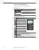
Control Scheme
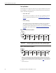
Change from 3-wire Start/Stop to 2-wire Run/Not Run at Digital In 1 and
Digital In 2.
1. Set Parameter 361 [Digital In1 Sel] to option 7 Run, or 9 Run Reverse.
2. Set Parameter 362 [Digital In2 Sel] to another option such as 8 Run
Forward, or 10 Jog.
See I/O wiring examples beginning on page 35
.
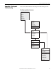
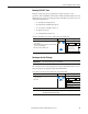
Restoring Factory Defaults
From the HIM Main Menu, select Memory Storage/Reset To Defaults.
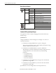
Troubleshooting – Abbreviated Fault and Alarm Listing
For a complete listing of faults and alarms, refer to the PowerFlex 70 User
Manual, publication 20A-UM001
.
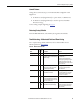
Table 21 - Abbreviated Fault Table
Fault
No.
Type
(1)
Description Action
Auxiliary Input 2 ➊ Auxiliary input interlock is open. Check remote wiring.
Decel Inhibit 24
➌ The drive is not following a commanded
deceleration because it is attempting to
limit bus voltage.
Verify input voltage is within drive
specified limits.
Verify system ground impedance
follows proper grounding techniques.
Disable bus regulation and/or add
dynamic brake resistor and/or extend
deceleration time.
FluxAmpsRef Rang 78 The value for flux amps determined by
the Autotune procedure exceeds the
programmed [Motor NP FLA].
Reprogram [Motor NP FLA] with the
correct motor nameplate value.
Repeat Autotune.
HW OverCurrent 12
➊ The drive output current has exceeded
the hardware current limit.
Check programming. Check for excess
load, improper DC boost setting, DC
brake volts set too high or other
causes of excess current.
IR Volts Range 77 “Calculate” is the autotune default and
the value determined by the autotune
procedure for IR Drop Volts is not in the
range of acceptable values.
Re-enter motor nameplate data.
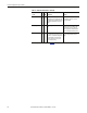
Motor Overload 7
➊
➌
Internal electronic overload trip.
Enable/Disable with [Fault Config 1].
An excessive motor load exists.
Reduce load so drive output current
does not exceed the current set by
[Motor NP FLA].