
User guide

42 Rockwell Automation Publication 20A-IN009D-EN-P - June 2013
PowerFlex 70 Adjustable Frequency AC Drive
5. Apply AC power and control voltages to the drive.
If the STS LED is not flashing green at this point, refer to Drive Status
Indicators on page 48.
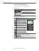
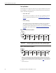
6. When prompted, select a display language.
The PowerFlex 70 start-up screen displays.
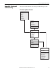
7. Press the enter key to display the start-up menu.
8. Use the arrow keys to highlight 2. Basic.
9. Press the enter key.
Use the enter key to follow the menu and step you through the start-up
routine.
The basic start-up routine asks simple questions and prompts you to input
required information. See also Common I/O Programming Changes
on page 48.
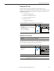
Information About Start-up Motor Tests
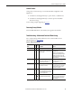
Control schemes vary based on the Start/Jog Source that is selected in Step 3.
Motor Tests.
During motor tests and tuning procedures, the drive can modify certain
parameter values for proper start-up operation. These values are reset to their
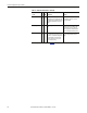
original values when startup is complete. The affected parameters are listed here:
• 053
• 080
• 276
• 278
• 361…366
IMPORTANT
If any of the six digital inputs are configured to Stop – CF (CF = Clear
Fault) or Enable, verify that signals are present or the drive can not
start. Refer to Troubleshooting – Abbreviated Fault and Alarm Listing
on page 49 for a list of potential digital input conflicts.
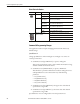
Start/Jog Source Control Source Description
Digital inputs Digital In 1 = Stop / Digital In 2 = Start / Digital In 3 = Jog
Local HIM – Port 1 HIM connected to DPI Port 1 controls Stop / Start / Jog
Digital In 1…6 are temporarily disabled during motor tests.
Remote HIM HIM connected to DPI Port 2 controls Stop / Start / Jog
Digital In 1…6 are temporarily disabled during motor tests.
IMPORTANT
If power is removed from the drive during the tests without aborting the
auto-tune procedure, these parameters may not reset to their original value. If
this situation occurs, reset the drive to factory defaults (see page 49
) and
repeat the start-up procedure.