Installation Instructions PowerFlex 70 Adjustable Frequency AC Drive 0.37…37 kW (0.5…50 Hp) This document explains the 5 BASIC STEPS needed to install and perform a Basic Start-Up of the PowerFlex 70 AC drive. A Human Interface Module (HIM) is required to perform the Basic Start-Up routine covered in this manual. The information provided is intended for qualified installers only. Additional Resources These documents contain additional information concerning related products from Rockwell Automation.
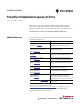
PowerFlex 70 Adjustable Frequency AC Drive Allen-Bradley Drives Technical Support Use the contacts below for PowerFlex 70 technical support including spare parts information. Installation Instructions in Other Languages 2 Online at… By Email at… By Telephone at… http://www.ab.com/support/abdrives support@drives.ra.rockwell.com 262-512-8176 Language Download Instructions English This instruction sheet is available in multiple languages at http://www.rockwellautomation.com/literature.
PowerFlex 70 Adjustable Frequency AC Drive Table of Contents Catalog Number Explanation . . . . . . . . . . . . . . . . . . . . . . . . . . . . . . . . . . . . . . . . . . . . . 4 Step 1: Read the Precautions and General Information . . . . . . . . . . . . . . . . . . . . . 6 EMC Instructions . . . . . . . . . . . . . . . . . . . . . . . . . . . . . . . . . . . . . . . . . . . . . . . . . . . . . . . 8 Step 2: Mount the Drive – Minimum Requirements . . . . . . . . . . . . . . . . . . . . . . .
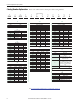
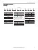
PowerFlex 70 Adjustable Frequency AC Drive Catalog Number Explanation Refer to the table below for a description of the catalog numbers. Position Number 1-3 4 5-7 8 9 10 11 12 13 14 15 16 20A B 2P2 A 3 A Y Y N N C 0 a b c d e f g h i j k l a c3 c5 Drive ND Rating ND Rating Code Type 20A PowerFlex 70 400V, 50 Hz Input kW (Hp) 1P3 1.3 0.37 (0.5) 2P1 2.1 3P5 600V, 60 Hz Input Frame Amps kW (Hp) A 0P9 0.9 0.37 (0.5) 0.75 (1.0) A 1P7 1.7 0.75 (1.
PowerFlex 70 Adjustable Frequency AC Drive Catalog Number Explanation (continued) Position Number 1-3 4 5-7 8 9 10 11 12 13 14 15 16 20A B 2P2 A 3 A Y Y N N C 0 a b c d e f g h i j k l f i k Documentation Emission Class Control & I/O Code Type A Manual N No Manual g Code Rating Code Control Safe-Off N Standard A Filtered A & B Frames (Optional) C, D, & E Frames (Standard) N/A C Enhanced No G Enhanced Yes N Not Filtered A & B Frames (Optional
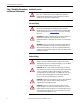
PowerFlex 70 Adjustable Frequency AC Drive Step 1: Read the Precautions Qualified Personnel and General Information ATTENTION: Only qualified personnel familiar with adjustable frequency AC drives and associated machinery can plan or implement the installation, startup, and subsequent maintenance of the system. Failure to comply can result in personal injury and/or equipment damage.
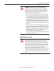
PowerFlex 70 Adjustable Frequency AC Drive ATTENTION: The “adjust freq” portion of the bus regulator function is extremely useful for preventing nuisance overvoltage faults resulting from aggressive decelerations, overhauling loads, and eccentric loads. It forces the output frequency to be greater than commanded frequency while the drive’s bus voltage is increasing towards levels that can cause a fault; however, it can also cause either of the following two conditions to occur.
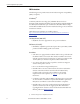
PowerFlex 70 Adjustable Frequency AC Drive EMC Instructions The following section provides instructions for Electromagnetic Compatibility (EMC) compliance. CE Conformity(1) Conformity with the Low Voltage (LV) and EMC directive has been demonstrated by using harmonized European Norm (EN) standards published in the Official Journal of the European Communities. PowerFlex Drives comply with the EN standards listed below when installed according to the user manuals and reference manuals.
PowerFlex 70 Adjustable Frequency AC Drive Essential Requirements for CE Compliance These six conditions must be satisfied for PowerFlex drives to meet the requirements of EN61800-3: • Standard PowerFlex 70 CE compatible drive. • Review important precautions/attention statements throughout this manual before installing the drive. • Ground the drive as described in General Grounding Requirements on page 22.
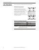
PowerFlex 70 Adjustable Frequency AC Drive Step 2: Mount the Drive – Minimum Requirements This section describes the minimum requirements to mount the drive. Minimum Mounting Clearances Specified vertical clearance requirements are intended to be from the drive to the closest object that can restrict airflow through the drive heat sink and chassis. The drive must be mounted in a vertical orientation as shown, and must make full contact with the mounting surface. Do not use standoffs or spacers.
PowerFlex 70 Adjustable Frequency AC Drive Power Ratings, Dimensions, and Approximate Weights This section provides power ratings, dimensions, and weights for the drives. Table 2 - Power Ratings Output Power Frame Size 208…240V AC Input 400…480V AC Input 600V AC Input kW ND (HD) Hp ND (HD) Not Filtered (1) Filtered (2) IP66 NEMA/UL Type 4X/12 (3) Not Filtered (1) Filtered (2) IP66 NEMA/UL Type 4X/12 (3) Not Filtered (1) Filtered (2) IP66 NEMA/UL Type 4X/12 (3) 0.37 (0.25) 0.5 (0.
PowerFlex 70 Adjustable Frequency AC Drive Figure 1 - Dimension Drawings IP20 and IP66 NEMA/UL Type 1 and 4X/12 A D Flange Mount A C E C B B F D E Table 3 - Dimensions and Approximate Weights Dimensions, mm (in.) Frame A B C D E F Weight (1) kg (lb) IP20 NEMA/UL Type 1 A 122.4 (4.82) 225.7 (8.89) 179.8 (7.08) 94.2 (3.71) 211.6 (8.33) 5.8 (0.23) 2.71 (6.0) B 171.7 (6.76) 234.6 (9.24) 179.8 (7.08) 122.7 (4.83) 220.2 (8.67) 5.8 (0.23) 3.60 (7.9) C 185.0 (7.28) 300.0 (11.
PowerFlex 70 Adjustable Frequency AC Drive Figure 2 - PowerFlex 70 IP20 NEMA/UL Type 1 Bottom View Dimensions, mm (in.) Frame A Frame B (For some drive ratings, the fan is not present.) 86.4 (3.40) 34.5 (1.36) 23.9 (0.94) 127.5 (5.02) 22.2 (0.87) Dia. 4 Places 43.4 (1.71) 32.8 (1.29) 22.2 (0.87) Dia. 5 Places 155.2 (6.11) 155.2 (6.11) 135.9 (5.35) 163.7 (6.45) 136.7 (5.38) 163.7 (6.45) 126.2 (4.97) 101.6 (4.00) 129.8 (5.11) 102.4 (4.03) 55.6 (2.19) 42.7 (1.68) 75.5 (2.97) 85.7 (3.37) 113.
PowerFlex 70 Adjustable Frequency AC Drive Figure 3 - PowerFlex 70 IP 66 NEMA/UL Type 4X/12 Bottom View Dimensions, mm (in.) (for indoor use only) Frame B Frame D 28.3 (1.11) 28.3 (1.11) 22.1 (0.87) 140.5 (5.53) 138.2 (5.44) 138.6 (5.46) 99.6 (3.92) 102.9 (4.05) 31.0 (1.22) 49.1 (1.93) 55.2 (2.17) 77.3 (3.04) 99.6 (3.92) 115.9 (4.56) 75.5 (2.97) 102.0 (4.02) 120.1 (4.73) Figure 4 - PowerFlex 70 IP 54 / IP 66 NEMA/UL Type 4X/12 Bottom View Dimensions, mm (in.) Frame E 22.5 (0.89) 44.5 (1.
PowerFlex 70 Adjustable Frequency AC Drive Figure 5 - PowerFlex 70 Flange Mount Bottom View Dimensions, mm (in.) Frame A 103.2 (4.06) Frame C 129.3 (5.09) 75.4 (2.97) 22.2 (0.87) Dia. 4 Places 51.3 (2.02) 40.7 (1.60) 22.2 (0.87) Dia. 4 Places 64.7 (2.55) 95.9 (3.78) 104.4 (4.11) 76.6 (3.02) 70.5 (2.78) 94.6 (3.72) 102.9 (4.05) 68.7 (2.70) 43.2 (1.70) 40.6 (1.60) 59.6 (2.35) 72.4 (2.85) 96.1 (3.78) 101.9 (4.01) 53.1 (2.09) 73.0 (2.87) 92.2 (3.63) 111.2 (4.38) Frame B Frame D 164.1 (6.
PowerFlex 70 Adjustable Frequency AC Drive Figure 6 - PowerFlex 70 Cutout Dimensions Frame A 156,0 (6.14) 205,2 (8.08) 140,7 (5.54) 70,7 (2.78) 6,9 (0.27) Frame B 127,0 (5.00) 219,0 (8.62) 190,0 (7.48) 95,0 (3.74) 6,9 (0.27) Frame C 6,3 (0.25) 202,0 (7.95) 101,0 (3.98) 176,3 (6.94) 300,0 (11.81) 189,4 (7.46) 225,8 (8.89) 210,6 (8.29) 197.9 (7.80) 234,6 219,3 (9.24) (8.63) 205,5 (8.09) 283,0 (11.14) 272,3 (10.72) 241,5 (9.51) 105,3 (4.15) 109,7 (4.32) 141,5 (5.57) 41,5 (1.
PowerFlex 70 Adjustable Frequency AC Drive Step 3: Wire the Drive – Wire Recommendations This section describes wiring recommendations for the drive. Opening the Cover To open the cover, follow the steps for your drive enclosure shown below. IP20 NEMA/UL Type 1 1. Loosen the cover screw. 2. Pull the cover straight off the chassis to avoid damaging the connector pins. IP66 NEMA/UL Type 4X/12 (for indoor use only) 1. Loosen the cover screws. IMPORTANT 2. Pull the cover straight off the chassis.
PowerFlex 70 Adjustable Frequency AC Drive Table 4 - Wiring Specifications Type Power Description Standard 600V, 90 °C (194 °F) XHHW2/RHW-2 Anixter B209500-B209507, Belden 29501-29507, (or equivalent) Four tinned copper conductors with XLPE insulation. Copper braid/aluminum foil combination shield and tinned copper drain wire. PVC jacket. – Standard analog I/O Belden 8760/9460 (or equivalent) 0.750 mm2 (18 AWG), twisted pair, 100% shield with drain. Belden 8770 (or equivalent) 0.
PowerFlex 70 Adjustable Frequency AC Drive Input Power Conditioning Some events on the power system supplying a drive can cause component damage or shortened product life. These events are divided into two basic categories that are described below: • All Drives – The power system has power factor correction capacitors switched in and out of the system, either by the user or by the power company. – The power source has intermittent voltage spikes in excess of 6000V.
PowerFlex 70 Adjustable Frequency AC Drive Power Terminal Block Figure 7 - Typical Power Terminal Block Location (B frame shown) IP 20 (NEMA/UL Type 1) IP 66 (NEMA/UL Type 4X/12) Table 5 - Power Terminal Block Specifications Wire Size Range (1) Max mm2 (AWG) Min Max Recommended mm2 (AWG) N•m (lb•in) N•m (lb•in) Input power and motor connections 4.0 (10) 0.3 (22) 1.1 (10) 0.8 (7) D Input power and motor connections 10.0 (6) 0.8 (18) 1.7 (15) 1.4 (12) E Input power and motor connections 25.
PowerFlex 70 Adjustable Frequency AC Drive Cable Entry Plate Removal If additional wiring access is needed, the cable entry plate on all drive frames can be removed. Loosen the screws securing the plate to the heat sink and slide the plate out.
PowerFlex 70 Adjustable Frequency AC Drive General Grounding Requirements IMPORTANT The safety ground for the drive (PE) must be connected to system ground. Ground impedance must conform to the requirements of national and local industrial safety regulations and/or electrical codes. Check the integrity of all ground connections periodically. For installations within a cabinet, a single safety ground point or ground bus bar connected directly to building steel (girder, joist) can be used.
PowerFlex 70 Adjustable Frequency AC Drive RFI Filter Grounding Use RFI filters only in installations with grounded AC supply systems that are permanently installed and solidly grounded (bonded) to the building power distribution ground. IMPORTANT If you use an optional radio-frequency interference (RFI) filter, relatively high ground leakage currents can be present. Be sure that the incoming supply neutral is solidly connected (bonded) to the same building power distribution ground.
PowerFlex 70 Adjustable Frequency AC Drive Shielded/Armored Cable Shielded cable contains all of the general benefits of multi-conductor cable with the added benefit of a copper braided shield that can contain much of the noise generated by a typical AC Drive. Use shielded cable for installations with sensitive equipment such as weigh scales, capacitive proximity switches, and other devices that can be affected by electrical noise in the distribution system.
PowerFlex 70 Adjustable Frequency AC Drive Motor Cable Lengths Typically, motor lead lengths less than 30 m (approximately 100 ft) are acceptable. However, if your application requires longer lengths, refer to Wiring and Grounding Guidelines for Pulse Width Modulated (PWM) AC Drives, publication DRIVES-IN001, for details. Motor Overload Protection Class 10 motor overload protection according to NEC article 430 and motor over-temperature protection according to NEC article 430.126 (A)(2).
PowerFlex 70 Adjustable Frequency AC Drive Frame(1) Table 8 - 208/240 Volt AC Three-phase Input Drive Ratings and Input Protection Devices Hp Rating ND HD Cat.No. 208 Volt AC Input 20AB2P2 A 0.5 0.33 20AB4P2 A 1 0.75 20AB6P8 B 2 1.5 20AB9P6 B 3 2 20AB015 C 5 3 20AB022 D 7.5 5 20AB028 D 10 7.5 20AB042 D 15 10 20AB054 E 20 15 20AB070 E 25 20 240 Volt AC Input 20AB2P2 A 0.5 0.33 20AB4P2 A 1 0.75 20AB6P8 B 2 1.5 20AB9P6 B 3 2 20AB015 C 5 3 20AB022 D 7.5 5 20AB028 D 10 7.
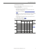
PowerFlex 70 Adjustable Frequency AC Drive Frame(1) Table 9 - 400/480 Volt AC Three-phase Input Drive Ratings and Input Protection Devices (continued) Hp Rating ND HD Cat.No. 20AD022 D 15 10 20AD027 D 20 15 20AD034 D 25 20 20AD040 D 30 25 20AD052 E 40 30 20AD065 E 50 40 See page 29 for notes. Dual Input Element Time Non-time Circuit Ratings Output Amps Delay Fuse Delay Fuse Breaker (4) Amps kVA Cont. 1 Min. 3 Sec. Min (2) Max (3) Min (2) Max (3) Max(5) 19.9 24.8 31.2 36.7 47.7 59.6 16.6 20.6 25.9 30.
PowerFlex 70 Adjustable Frequency AC Drive Frame(1) Table 11 - 208/240 Volt AC Single-phase Input Drive Ratings and Input Protection Devices (continued) Hp Rating ND HD Cat.No. 20AB9P6 B 3 2 20AB015 C 5 3 20AB022 D 7.5 5 20AB028 D 10 7.5 20AB042 D 15 10 20AB054 E 20 15 20AB070 E 25 20 See page 29 for notes. Dual Input Element Time Non-time Circuit Ratings Output Amps Delay Fuse Delay Fuse Breaker (4) Amps kVA Cont. 1 Min. 3 Sec. Min (2) Max (3) Min (2) Max (3) Max(5) 12.2 13.9 19.9 25.7 38.7 49.8 64.
PowerFlex 70 Adjustable Frequency AC Drive Frame(1) Table 13 - 600 Volt AC Single-phase Input Drive Ratings and Input Protection Devices Dual Hp Input Element Time Non-time Circuit Rating Ratings Output Amps Delay Fuse Delay Fuse Breaker (4) ND HD Amps kVA Cont. 1 Min. 3 Sec. Min (2) Max (3) Min (2) Max (3) Max(5) Cat. No. 600 Volt AC Input 20AE0P9 A 0.5 20AE1P7 A 1 20AE2P7 A 2 20AE3P9 B 3 20AE6P1 B 5 20AE9P0 C 7.
PowerFlex 70 Adjustable Frequency AC Drive IMPORTANT To guard against unstable operation and/or damage, you must configure the drive as shown in Table 14 on page 30. The PowerFlex 70 drive contains protective MOVs and common mode capacitors referenced to ground (see below).
PowerFlex 70 Adjustable Frequency AC Drive To connect or disconnect these devices, refer to pages 32 through 34. IMPORTANT Common mode capacitors are required to conform with the EMC directive. Removing the common mode capacitors causes the drive to be non-compliant with the EMC directive.
PowerFlex 70 Adjustable Frequency AC Drive Jumper Settings and Locations Frame Voltage Code Factory Default Jumper Settings DC Bus Common Mode MOV/Input Filter Caps Caps Power Source Type B C D E JP2/JP3 Installed Not applicable JP2 JP3 Solid ground Insert jumper at the “JP2/JP3” location. Non-solid ground Remove the jumper at “JP2/JP3.
Frame Voltage Code PowerFlex 70 Adjustable Frequency AC Drive Factory Default Jumper Settings DC Bus Common Mode MOV/Input Filter Caps Caps Power Source Type B D E JP2/JP3 Installed JP3A/JP3B Not installed C JP2/JP3 Installed JP3A/JP3B Installed CM Cap JP3B JP3A Solid ground Install jumpers at both locations (JP2/JP3 and JP3A/JP3B).
Frame Voltage Code PowerFlex 70 Adjustable Frequency AC Drive Factory Default Jumper Settings DC Bus Common Mode MOV/Input Filter Caps Caps Power Source Type B D E JP1/JP2 Installed JP3/JP4 Not installed C JP1/JP2 Installed JP3/JP4 Installed CM Cap JP4 JP1 JP2 JP3 MOV / Filter Cap E 34 Rockwell Automation Publication 20A-IN009D-EN-P - June 2013 Solid ground Install jumpers at both locations (JP1/JP2 and JP3/JP4). Non-solid ground Remove the jumper at “JP1/JP2.
PowerFlex 70 Adjustable Frequency AC Drive Step 4: I/O Wiring Important points to remember about I/O wiring: • Use copper wire. Wire gauge requirements and recommendations are based on 75 °C (167 °F). Do not reduce wire gauge when you are using higher temperature wire. • Wire with an insulation rating of 600V or greater. • Control and signal wires must be separated from power wires by at least 0.3 m (1 ft).
PowerFlex 70 Adjustable Frequency AC Drive I/O Terminal Positions Table 17 - I/O Terminal Designations – Standard and Enhanced Control Related Parameters No. Signal Factory Default Description 1 Digital In 1 Stop – CF (CF = Clear Fault) 361…366 2 Digital In 2 Start 3 Digital In 3 Auto/Man 4 Digital In 4 Speed Sel 1 5 Digital In 5 Speed Sel 2 11.2 mA at 24V DC 19.2V minimum on state 3.2V maximum off state Important: Use only 24V DC, not suitable for 115V AC circuitry.
PowerFlex 70 Adjustable Frequency AC Drive I/O Wiring Examples This section shows examples of typical I/O wiring. Input/Output Connection Example Required Parameter Settings Potentiometer unipolar speed reference 10k Ohm pot. recommended (2k Ohm minimum) 18 19 22 10 Analog input unipolar speed reference 0…+10V Input Select speed reference source: Param. 090 = 2 “Analog In 2” Adjust Scaling: Param. 091, 092, 322, 323 Check results: Param. 017 Default speed reference source: 18 Param.
PowerFlex 70 Adjustable Frequency AC Drive Input/Output Connection Example Required Parameter Settings Enable input Shown in enabled state. Important: Digital inputs are not designed to work with a pulsed source. Standard control Param. 366 = 1 “Enable” Enhanced control Param.
PowerFlex 70 Adjustable Frequency AC Drive Hardware Enable Circuitry (only enhanced control) By default, you can program a digital input as an enable input. The status of this input is interpreted by drive software. If the application requires the drive to be disabled without software interpretation, a hardware enable configuration is used. To use the hardware enable configuration, remove the enable jumper (ENBL JMP) and wire the enable input to Digital In 6 (see below). 1. Remove the drive cover. 2.
PowerFlex 70 Adjustable Frequency AC Drive For detailed information on installing and wiring a safety relay system, refer to the DriveGuard Safe Torque Off Option (Series B) for PowerFlex 40P and PowerFlex 70 AC Drives User Manual, publication PFLEX-UM003. If the Safe Torque Off board is removed from the drive, pins 3 and 4 of the Safe Torque Off connector must be jumpered for the drive to run.
PowerFlex 70 Adjustable Frequency AC Drive Table 20 - Encoder Specifications Description Type Incremental, dual-channel Supply 5V/12V Configurable ±5% Quadrature 90° ±27° Duty Cycle 50% +10% Requirements Encoders must be line driver type, quadrature (dual channel) or pulse (single channel), singleended or differential and capable of supplying a minimum of 10 mA per channel. The encoder interface board accepts 5V or 12V DC square-wave with a minimum high state voltage of 3.5V DC (5V mode) and 7.
PowerFlex 70 Adjustable Frequency AC Drive 5. Apply AC power and control voltages to the drive. IMPORTANT If any of the six digital inputs are configured to Stop – CF (CF = Clear Fault) or Enable, verify that signals are present or the drive can not start. Refer to Troubleshooting – Abbreviated Fault and Alarm Listing on page 49 for a list of potential digital input conflicts. If the STS LED is not flashing green at this point, refer to Drive Status Indicators on page 48. 6.
PowerFlex 70 Adjustable Frequency AC Drive Appendix A: Startup and Troubleshooting This section includes information for starting and troubleshooting the drive. First Power-up Menu Structure English? Français? ¿Español? Italiano? Deutsch? Português? Nederlands? Not Selected Main Menu: Diagnostics Parameter Device Select Memory Storage Start-Up Preferences PowerFlex 70 Start-Up Startup consists of several steps to configure a drive for basic applications. PowerFlex 70 Start-Up Make a selection 1.
PowerFlex 70 Adjustable Frequency AC Drive Human Interface Module (HIM) Overview This section provides information for operating the HIM. LCD Display Elements Display Description F-> Power Loss Auto Direction⎥ Drive Status⎥ Alarm⎥ Auto/Man⎥ Information 0.
PowerFlex 70 Adjustable Frequency AC Drive Human Interface Module (HIM) Main Menu Main Menu Screen F-> Power Loss Menu Selections Auto 0.0 Hz Main Menu: Diagnostics Parameter Device Select Main Menu: Diagnostics Parameter Device Select Memory Storage Start-Up Preferences ALT Functions To use an ALT function, start at the Main Menu and press the ALT key, release it, then press the programming key associated with one of the following functions listed in the table below.
PowerFlex 70 Adjustable Frequency AC Drive Start-up Routines The PowerFlex 70 is designed so that startup is simple and efficient. If you have an LCD HIM, two start-up methods are provided. Select the desired start-up routine needed for the application: • S.M.A.R.T. Start This routine lets you quickly set up the drive by programming values for the most commonly used functions (see Running S.M.A.R.T. Start on page 47).
PowerFlex 70 Adjustable Frequency AC Drive Running S.M.A.R.T. Start During a startup, the majority of applications require changes to a few parameters. The LCD HIM on a PowerFlex 70 drive offers S.M.A.R.T. start, and displays the most commonly changed parameters. With these parameters you can set the following functions: • S – Start Mode and Stop Mode • M – Minimum and Maximum Speed • A – Accel Time 1 and Decel Time 1 • R – Reference Source • T – Thermal Motor Overload To run a S.M.A.R.T.
PowerFlex 70 Adjustable Frequency AC Drive Drive Status Indicators Name Color State Description Green Flashing The d rive is ready but is not running, and no faults are present. Steady The drive is running and no faults are present. Flashing, drive stopped An inhibit condition exists, the drive cannot be started. Check parameter 214 [Start Inhibits]. Flashing, drive running An intermittent type 1 alarm condition exists. Check parameter 211 [Drive Alarm 1].
PowerFlex 70 Adjustable Frequency AC Drive Control Scheme Change from 3-wire Start/Stop to 2-wire Run/Not Run at Digital In 1 and Digital In 2. 1. Set Parameter 361 [Digital In1 Sel] to option 7 Run, or 9 Run Reverse. 2. Set Parameter 362 [Digital In2 Sel] to another option such as 8 Run Forward, or 10 Jog. See I/O wiring examples beginning on page 35. Restoring Factory Defaults From the HIM Main Menu, select Memory Storage/Reset To Defaults.
PowerFlex 70 Adjustable Frequency AC Drive Fault OverSpeed Limit 25 Type(1) No. Table 21 - Abbreviated Fault Table (continued) Description ➊ Functions such as Slip Compensation or Bus Regulation have attempted to add an output frequency adjustment greater than that programmed in [Overspeed Limit]. OverVoltage 5 ➊ DC bus voltage exceeded maximum value. SW OverCurrent 36 ➊ Drive output current has exceeded the 1ms current rating.
PowerFlex 70 Adjustable Frequency AC Drive Dig In ConflictA 17 Type(1) Alarm No. Table 22 - Abbreviated Alarm Table 2 Description Digital input functions are in conflict. Combinations marked with an “X” will cause an alarm.
PowerFlex 70 Adjustable Frequency AC Drive Common Symptoms and Corrective Actions Table 23 - Drive Does Not Start From Start or Run Inputs Wired to the Terminal Block Cause Indication Corrective Action Drive is Faulted Flashing red status light Clear fault. • Press Stop • Cycle power • Set [Fault Clear] to 1 • “Clear Faults” on the HIM Diagnostic menu Flashing green Incorrect input wiring. status light See page 35 for wiring examples.
PowerFlex 70 Adjustable Frequency AC Drive Table 25 - Drive Does Not Respond to Changes in Speed Command Cause Indication Corrective Action No value is coming from the source of the command. LCD HIM Status Line indicates “At Speed” and output is 0 Hz. 1. If the source is an analog input, check wiring and use a meter to check for presence of signal. 2. Check [Commanded Freq] for correct source. Incorrect reference source has been programmed. None 1.
PowerFlex 70 Adjustable Frequency AC Drive Notes: 54 Rockwell Automation Publication 20A-IN009D-EN-P - June 2013
PowerFlex 70 Adjustable Frequency AC Drive Notes: Rockwell Automation Publication 20A-IN009D-EN-P - June 2013 55
Rockwell Automation Support Rockwell Automation provides technical information on the Web to assist you in using its products. At http://www.rockwellautomation.com/support, you can find technical manuals, technical and application notes, sample code and links to software service packs, and a MySupport feature that you can customize to make the best use of these tools. You can also visit our Knowledgebase at http://www.rockwellautomation.