
Owner's manual

Publication 2099-IN002B-EN-P — October 2008
10 Kinetix 7000 DC-DC Converter and Control Board Kits
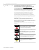
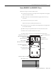
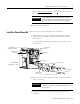
4. Remove the connector plate.
5. Remove the two connector plate stand-offs by using a 1/4 in.
thin-walled socket, nut driver, or open-ended wrench.
6. Remove the five control board screws.
7. Remove and replace the control board.
Verify the control board pins are fully inserted into display board.
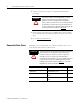
8. Replace the screws, stand-offs, connector plate, and ribbon cable as
described in steps 1...6 above.
9. Replace the dc-dc converter cassette cover and drive covers.
Refer to Remove the Drive Covers
on page 4 and reverse the order of
steps for your drive module.
10. Return the drive to operation.
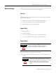
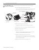
ATTENTION
To avoid damage to small components adjacent to the
stand-offs, use a thin-walled socket or open-ended wrench
to remove the stand-offs.
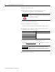
Screw Torque Value
Connector plate stand-offs (2x)
0.68 N•m (6.0 in
•lb)
Connector plate screws (2x)
Connector stand-offs (6x)
Control board screws (5x)
IMPORTANT
When replacing the top cover, temporarily remove the
fiber-optic cables from the drive Tx and Rx connectors. This
allows the top cover to seat properly with the chassis.