Installation Instructions Kinetix 7000 DC-DC Converter and Control Board Kits Catalog Numbers 2099-K7KCP-1, 2099-K7KCB-1 About This Publication Topic Page About This Publication 1 Before You Begin 3 Remove the Drive Covers 4 Install the DC-DC Converter Kit 8 Install the Control Board Kit 9 Replace the DC-DC Converter Fuse 11 Additional Resources 12 This publication provides information for removing and replacing the dc-dc converter, dc-dc converter fuse, and the control board assembly on
Kinetix 7000 DC-DC Converter and Control Board Kits Important User Information Solid state equipment has operational characteristics differing from those of electromechanical equipment. Safety Guidelines for the Application, Installation and Maintenance of Solid State Controls (publication SGI-1.1 available from your local Rockwell Automation sales office or online at http://literature.rockwellautomation.
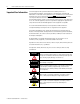
Kinetix 7000 DC-DC Converter and Control Board Kits Before You Begin 3 Make sure you have the following spare parts, tools, and have removed power so you can safely remove the drive covers and assemblies.
Kinetix 7000 DC-DC Converter and Control Board Kits 2. Allow five minutes for the dc bus to completely discharge before proceeding. ATTENTION This product contains stored energy devices. To avoid hazard of electrical shock, verify that all voltage on capacitors has been discharged before attempting to service, repair, or remove this unit.
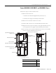
Kinetix 7000 DC-DC Converter and Control Board Kits 5 Remove 2099-BM06-S, 2099-BM07-S, and 2099-BM08-S Covers Follow these steps to remove the drive covers. 1. Remove the bottom cover. a. Pull the cover downward approximately 12 mm (0.5 in.). b. Pull the cover straight out and away from the drive. 2. Remove the two dc-dc converter cover screws. 3. Pull the dc-dc converter cover outward and away from the drive. 4.
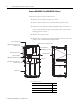
Kinetix 7000 DC-DC Converter and Control Board Kits Remove 2099-BM09-S and 2099-BM10-S Covers Follow these steps to remove the drive covers. 1. Remove the two dc-dc converter cover screws. 2. Pull the dc-dc converter cover outward and away from the drive. 3. Pull the top cover fastener rod upward approximately 12 mm (0.5 in.). If the rod is pulled far enough, the three latch points on the rod will disengage with the chassis. 4. Remove the top cover screw. 5.
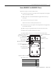
Kinetix 7000 DC-DC Converter and Control Board Kits 7 Remove 2099-BM11-S and 2099-BM12-S Covers Follow these steps to remove the drive covers. 1. Loosen the two bottom-cover captive screws and pull the cover slightly away from the drive module. 2. Slide the bottom cover downward until the upper tabs clear the top cover slots. 3. Loosen the two lower-top cover screws. These screws were covered by the bottom cover. 4.
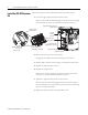
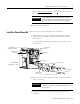
Kinetix 7000 DC-DC Converter and Control Board Kits Install the DC-DC Converter Kit Follow these steps to remove and replace the dc-dc converter cassette. 1. Loosen the upper and lower dc-dc converter screws. Turn the screws until the latch disengages from the cassette. The upper screw and latch are shown, the lower screw latches the same way.
Kinetix 7000 DC-DC Converter and Control Board Kits 9 Refer to Remove the Drive Covers on page 4 and reverse the order of steps for your drive module. When replacing the top cover, temporarily remove the fiber-optic cables from the drive Tx and Rx connectors. This allows the top cover to seat properly with the chassis. IMPORTANT 8. Return the drive to operation. Install the Control Board Kit Follow these steps to remove and replace the control board. 1.
Kinetix 7000 DC-DC Converter and Control Board Kits 4. Remove the connector plate. 5. Remove the two connector plate stand-offs by using a 1/4 in. thin-walled socket, nut driver, or open-ended wrench. ATTENTION To avoid damage to small components adjacent to the stand-offs, use a thin-walled socket or open-ended wrench to remove the stand-offs. 6. Remove the five control board screws. 7. Remove and replace the control board. Verify the control board pins are fully inserted into display board. 8.
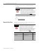
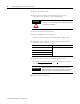
Kinetix 7000 DC-DC Converter and Control Board Kits Replace the DC-DC Converter Fuse 11 To access the dc-dc converter fuse, the dc-dc converter cassette cover must be removed. 1. Remove the dc-dc converter cassette cover. Refer to Remove the Drive Covers on page 4 and follow the procedure for your drive. DC-DC Converter Fuse DC-DC Converter Cassette LittelFuse 7.5 A, 32V dc PN 29707.5 Kinetix 7000 Drive (2099-BM07-S is shown) 2. Replace the fuse.
Kinetix 7000 DC-DC Converter and Control Board Kits Additional Resources The following documents contain additional information for this Rockwell Automation product and related products. Resource Description Kinetix 7000 High Power Servo Drives User Manual, publication 2099-UM001 Information on installing, configuring, startup, troubleshooting, and applications for your Kinetix 7000 servo drive system. LittelFuse, Inc. website http://littelfuse.com Replacement fuse datasheet for dc-dc converter.
Kinetix 7000 DC-DC Converter and Control Board Kits 13 Notes: Publication 2099-IN002B-EN-P — October 2008
Kinetix 7000 DC-DC Converter and Control Board Kits Notes: Publication 2099-IN002B-EN-P — October 2008
Kinetix 7000 DC-DC Converter and Control Board Kits 15 Notes: Publication 2099-IN002B-EN-P — October 2008
Rockwell Automation Support Rockwell Automation provides technical information on the Web to assist you in using its products. At http://support.rockwellautomation.com, you can find technical manuals, a knowledge base of FAQs, technical and application notes, sample code and links to software service packs, and a MySupport feature that you can customize to make the best use of these tools.