
Owner's manual

Publication 2098-RM001C-EN-P – August 2002
2-18 Programming Reference
Logic Command
The first two or four bytes in several Output Assemblies are referred
to as the Logic Command. The logic command bits correspond to
functions available via the hardware digital inputs on the Ultra3000
Drive with DeviceNet. Parameter 10 - Logic Command Mask allows
you to mask off (zero) selected Logic Command bits to prevent the
bits activating any functions.
Note: The Logic Command Mask has a default value of zero.
Therefore, the Logic Command has no affect unless you modify
the Logic Command Mask.
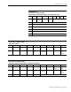
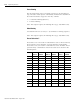
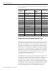
Assembly Object,
Instance ID = 9 - Output Assembly
32 Bit Logic Command, Handshake Bit, Feedback Data Pointer, and Parameter Data Value
Byte Bit 7 Bit 6 Bit 5 Bit 4 Bit 3 Bit 2 Bit 1 Bit 0
0 Reserved Reserved Reserved Abort Homing Pause
Homing
Abort
Indexing
Pause Index Disable Serial
1 Reserved Reserved Preset Select
5
Preset Select
4
Preset Select
3
Preset Select
2
Preset Select
1
Preset Select
0
2 Reserved Position
Strobe
Operation
Mode
Override
Reserved Reserved Follower
Enable
Integrator
Inhibit
Define
Position
3 Enable Reset Faults Start Homing Remove
Offset
Reserved Define Home Start Index Reset Drive
4 Write Data Save to
NVMEM
Handshake Reserved Feedback Data Pointer
5 Parameter Instance - Low Byte
6 Parameter Instance - High Byte
7 Data Value - Low Byte
8 Data Value - Low Middle Byte
9 Data Value - High Middle Byte
10 Data Value - High Byte