
Owner's manual

Publication 2098-RM001C-EN-P – August 2002
Programming Reference 2-13
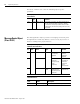
The following Assembly Objects are implemented in the drive and
buffer I/O in the following fashion:
• RO = Read Only
• R/W = Read/Write
• R/PW = Read/Write Protected.
Refer to the sections Output Assemblies on page 2-14 and Input
Assemblies on page 2-33 for detailed information about the various
instances of the Assembly Objects.
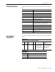
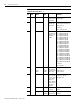
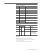
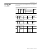
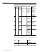
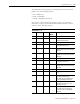
Assembly Object,
Instance ID = 1 - 18
ID Data Type Access Size
(Bytes)
Description
1 Static Output R/W 1 Handshake Bit, Feedback Data Pointer
2 Static Output R/W 7 Handshake Bit, Feedback Data Pointer,
and Parameter Data Value
3 Static Output R/PW 2 16 Bit Logic Command
4 Static Output R/PW 3 16 Bit Logic Command, Handshake Bit,
and Feedback Data Pointer
5 Static Output R/PW 8 16 Bit Logic Command, Handshake Bit,
Feedback Data Pointer, and Command
Data Value
6 Static Output R/PW 9 16 Bit Logic Command, Handshake Bit,
Feedback Data Pointer, and Parameter
Data Value
7 Static Output R/PW 4 32 Bit Logic Command
8 Static Output R/PW 5 32 Bit Logic Command, Handshake Bit,
and Feedback Data Pointer
9 Static Output R/PW 11 32 Bit Logic Command, Handshake Bit,
Feedback Data Pointer, and Parameter
Data Value
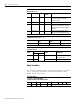
10 Static Input RO 4 32 Bit Logic Status
11 Static Input RO 8 32 Bit Logic Status, and Feedback Data
Value
12 Static Input RO 9 32 Bit Logic Status, Extra Status Byte
(with Write Data Status Bits,
Handshake Echo Bit, Feedback Data
Pointer) and Feedback Data Value
13 Static Input RO 5 32 Bit Logic Status, Extra Status Byte
(with Write Data Status Bits, and
Handshake Echo Bit)
14 Static Input RO 8 Alternate 32 Bit Logic Status with
Write Data Status Bits (replacing
Position Limits Bits), and Feedback
Data Value