Ultra3000 Digital Servo Drive with DeviceNet DeviceNet Firmware Version 1.
Important User Information Because of the variety of uses for the products described in this publication, those responsible for the application and use of this control equipment must satisfy themselves that all necessary steps have been taken to assure that each application and use meets all performance and safety requirements, including any applicable laws, regulations, codes and standards.
Table of Contents Preface Introduction . . . . . . . . . . . . . . . . Who Should Use this Manual . . . . Purpose of this Manual . . . . . . . . Contents of this Manual . . . . . . . . Related Documentation . . . . . . . . Conventions Used in this Manual . Allen-Bradley Support . . . . . . . . . Local Product Support . . . . . . Technical Product Assistance . . . . . . . . . . . . . . . . . . . . . . . . . . . . . . . . . . . . . . . . . . . . . . . . . . . . . . . . . . . . . . . . . . . . . . . .
ii Table of Contents Operation Mode Override . . . . . . . . . . . . . . . . . . . Reset Drive . . . . . . . . . . . . . . . . . . . . . . . . . . . . . . Start Index. . . . . . . . . . . . . . . . . . . . . . . . . . . . . . . Define Home. . . . . . . . . . . . . . . . . . . . . . . . . . . . . Remove Offset. . . . . . . . . . . . . . . . . . . . . . . . . . . . Start Homing . . . . . . . . . . . . . . . . . . . . . . . . . . . . . Reset Faults . . . . . . . . . . . . . . . . . . . . . . . . . . . . . .
Table of Contents Parameter Object (Class ID 0FH) . . . . . . . . . . . . . . . . . . . . 2-45 Get_Attribute_All Response . . . . . . . . . . . . . . . . . . . . . 2-95 Acknowledge Handler Object (Class ID 2BH) . . . . . . . . . .
iv Table of Contents Publication 2098-RM001C-EN-P – August 2002
Preface Introduction Read this preface to become familiar with the organization of the manual. In this preface, you will read about the following: • • • • • • Who Should Use this Manual Purpose of this Manual Contents of this Manual Related Documentation Conventions Used in this Manual Allen-Bradley Support Who Should Use this Manual This manual is intended for qualified service personnel responsible for setting up and servicing the Ultra3000 with DeviceNet.
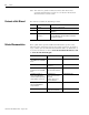
P-2 Preface Note: The reference guide to Ultra3000 drives with DeviceNet operating with firmware version 2.xx is listed in the Related Documentation section below. Contents of this Manual This manual contains the following sections: Chapter Related Documentation Title Contents Preface An overview of this manual. 1 Overview Describes network activity and drive configuration capabilities.
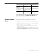
Preface For information about: Read this document: Publication Number A glossary of industrial automation terms and abbreviations Allen-Bradley Industrial Automation Glossary AG-7.1 How to commission a DeviceNet system. DeviceNet Cable System Planning and Installation Manual DN-6.7.2 An overview of Allen-Bradley motion controls and systems Motion Control Selection Guide GMC-SG001x-EN-P P-3 A copy of the DeviceNet Specification, Volumes I and II, Release 2.
P-4 Preface Allen-Bradley Support Allen-Bradley offers support services worldwide, with over 75 sales/support offices, 512 authorized distributors and 260 authorized systems integrators located throughout the United States alone, plus Allen-Bradley representatives in every major country in the world.
Chapter 1 Overview Introduction DeviceNet is an open, global industry-standard communication network. It is designed to provide an interface from a programmable controller through a single cable directly to smart devices such as sensors, push buttons, motor starters, simple operator interfaces and drives.
1-2 Overview Installing, Connecting, & Commissioning Ultra3000 Drives with DeviceNet This manual serves as a reference for configuring, monitoring, and controlling Ultra3000 Drives with DeviceNet.
Overview 1-3 Predefined Master/Slave Connection Set A set of messaging connections that facilitate communications and is typically seen in a master/slave relationship is known as the Predefined Master/Slave Connection set. The master is the device that gathers and distributes I/O data for the process controller. A DeviceNet master scans its slave devices based on a scan list it contains. Each slave device returns I/O data to its master device. The I/O data exchanged over this connection is pre-defined.
1-4 Overview I/O Messaging and Explicit Messaging with DeviceNet You can configure and monitor the drive with either I/O Messaging or Explicit Messaging. I/O messages are for time-critical, control-oriented data. I/O messages typically are used for moving predefined data repeatedly with minimum protocol overhead. Explicit Messages provide multi-purpose, point-to-point communication paths between two devices.
Overview Selecting Input and Output Assemblies for I/O Messages 1-5 The Ultra3000 Drive with DeviceNet allows you to choose between various Input and Output Assemblies, thereby choosing the data format of the messages that are passed back and forth between the drive and the master (scanner) on an I/O connection. The choice of which Input and Output Assembly to use should be based on what sort of information is appropriate in a particular system.
1-6 Overview Publication 2098-RM001C-EN-P – August 2002
Chapter 2 Programming Reference The Ultra3000 Drive with DeviceNet implements a vendor specific device profile - Rockwell Automation Miscellaneous (Device Type: 73hex). The configuration data and behaviors implemented in the Ultra3000 Drive with DeviceNet are defined using object modeling. The Ultra3000 Drive with DeviceNet is modeled as a collection of objects. An Object is a collection of related attributes and services.
2-2 Programming Reference Object Model The Object Model diagram on Page 2-2 depicts the objects supported in the Ultra3000 Drive with DeviceNet. The following table indicates the object classes present in this device, and the number of instances present in each class.
Programming Reference 2-3 How Objects Affect Behavior The objects in the Ultra3000 Drive with DeviceNet affect it’s behavior as shown in the table below.
2-4 Programming Reference Object Addressing The Media Access Control Identifier (MAC ID) is the common basis for logically addressing separate physical components across DeviceNet. The MAC ID is a unique integer assigned to each DeviceNet node that distinguishes it specifically from among other nodes on the same network. The MAC ID often is referred to as the node address.
Programming Reference Data Type Definitions Identity Object (Class ID 01 ) 2-5 The following mnemonics define the Ultra3000 with DeviceNet data types.
2-6 Programming Reference Identity Object, Attributes of Instance ID = 1 - 2 Attr. Access Attribute ID Rule Name Data Type Description 1 UINT Identification 01 = Rockwell Automation/ of each vendor Allen-Bradley by number 2 Get Vendor ID Device Type Indication of general type of product.
Programming Reference 2-7 Identity Object, Status Description of Attribute ID = 5 Bit (s) Description Semantics of Values 0 Owned TRUE = device has an owner 1 2 Reserved, set to 0 Configured Always = 0 3 Reserved, set to 0 4, 5, 6, 7 Vendor specific 8 Minor recoverable fault Always = 0 9 Minor unrecoverable fault Always = 0 10 Major recoverable fault TRUE if self diagnosis detects a major fault 11 Major unrecoverable fault Always = 0 12, 13 Reserved, set to 0 14, 15 Identity Obj
2-8 Programming Reference The Reset common service has the following object-specific parameter: Identity Object, Reset Service Message Router Object (Class ID 02 ) H Name Data Type Description Semantics of Values Type USINT Type of Reset 0 = Emulate as closely as possible cycling power of the item the Identity Object represents. (default) 1 = Return as closely as possible to the out-of-box configuration, then emulate cycling power as closely as possible.
Programming Reference DeviceNet Object (Class ID 03 ) 2-9 The DeviceNet Object provides configuration and status attributes of a DeviceNet port. H DeviceNet Object, Attribute of Instance ID = 0 (Class Attribute) Attr. ID Access Attribute Rule Name Data Description Type Semantics of Values 1 UINT Revision of the DeviceNet Object Class definition upon which the implementation is based. =2 Get Revision DeviceNet Object, Attributes of Instance ID = 1 Attr.
2-10 Programming Reference DeviceNet Object, Attributes of Instance ID = 1 (Continued) Attr. Access ID Rule Attribute Name 5 Allocation STRUCT of: information BYTE Get Data Type USINT Description Semantics of Values Allocation choice (1 byte) Refer to the DeviceNet Object definition in the DeviceNet Specification + Master MAC ID (1 byte) Range 0-63, 255 Modified via Allocate only.
Programming Reference 2-11 DeviceNet Object, Class Specific Services Assembly Object (Class ID 04 ) H Service Code Service Name Service Description 4BH Allocate_Master/Slave_ Connection_Set Requests the use of the Predefined Master/Slave Connection Set. 4CH Release_Group_2_ Identifier_Set Indicates that the specified Connections within the Predefined Master/Slave Connection Set are no longer desired. These connections are to be released (deleted).
2-12 Programming Reference IMPORTANT If the above parameters are modified, you must perform one of the following before the modified value(s) are active: •Close any existing I/O messaging connection(s) •Power cycle the drive •Reset the drive •Remove and reapply DeviceNet power to the drive. In addition, you can send Explicit Messages to the Input and Output Assemblies. Explicit Message writes to an Output Assembly can perform control functions.
Programming Reference 2-13 The following Assembly Objects are implemented in the drive and buffer I/O in the following fashion: • RO = Read Only • R/W = Read/Write • R/PW = Read/Write Protected. Refer to the sections Output Assemblies on page 2-14 and Input Assemblies on page 2-33 for detailed information about the various instances of the Assembly Objects.
2-14 Programming Reference Assembly Object, Instance ID = 1 - 18 ID Data Type Access Size (Bytes) Description 15 Static Input RO 4 Alternate 32 Bit Logic Status with Write Data Status Bits (replacing Position Limit Bits) 16 Static Input RO 4 Feedback Data Value 17 Static Input RO 5 Extra Status Byte (with Write Data Status bits, Handshake Echo Bit, and Feedback Data Pointer) and Feedback Data Value 18 Static Input RO 1 Extra Status Byte with Write Data Status Bits, and Handshake Ec
Programming Reference 2-15 Assembly Object, Instance ID = 2 - Output Assembly Handshake Bit, Feedback Data Pointer, and Parameter Data Value Byte Bit 7 Bit 6 Bit 5 Bit 4 0 Write Data Save to NVMEM Handshake 1 Parameter Instance - Low Byte 2 Parameter Instance - High Byte 3 Data Value - Low Byte 4 Data Value - Low Middle Byte 5 Data Value - High Middle Byte 6 Data Value - High Byte Bit 3 Bit 2 Bit 1 Bit 0 Feedback Data Pointer Assembly Object, Instance ID = 3 - Output Assembly 16
2-16 Programming Reference Assembly Object, Instance ID = 5 - Output Assembly 16 Bit Logic Command, Handshake Bit, Feedback Data Pointer, and Command Data Value Byte Bit 7 Bit 6 Bit 5 Bit 4 Bit 3 Bit 2 Bit 1 Bit 0 0 Preset Select 5 Preset Select 4 Preset Select 3 Preset Select 2 Preset Select 1 Preset Select 0 Follower Enable Integrator Inhibit 1 Enable Reset Faults Start Homing Remove Offset Disable Serial Define Home Communicati ons Start Index Operation Mode Override 2 Write
Programming Reference 2-17 Assembly Object, Instance ID = 7 - Output Assembly 32 Bit Logic Command Byte Bit 7 Bit 6 Bit 5 Bit 4 0 Reserved Reserved Reserved 1 Reserved Reserved 2 Reserved 3 Enable Bit 3 Bit 2 Bit 1 Bit 0 Abort Homing Pause Homing Abort Indexing Pause Index Disable Serial Preset Select 5 Preset Select 4 Preset Select 3 Preset Select 2 Preset Select 1 Preset Select 0 Position Strobe Operation Mode Override Reserved Reserved Follower Enable Integrator Inhib
2-18 Programming Reference Assembly Object, Instance ID = 9 - Output Assembly 32 Bit Logic Command, Handshake Bit, Feedback Data Pointer, and Parameter Data Value Byte Bit 7 Bit 6 Bit 5 Bit 4 0 Reserved Reserved Reserved 1 Reserved Reserved 2 Reserved 3 Bit 3 Bit 2 Bit 1 Bit 0 Abort Homing Pause Homing Abort Indexing Pause Index Disable Serial Preset Select 5 Preset Select 4 Preset Select 3 Preset Select 2 Preset Select 1 Preset Select 0 Position Strobe Operation Mode Overrid
Programming Reference 2-19 The Enable bit in the logic command is OR'ed or AND'ed with a hardware ENABLE as specified by Parameter 11 - Enable Behavior. • If the ENABLE function has not been assigned to a hardware input, then the hardware ENABLE is always active. • If any of the other functions have not been assigned to a hardware input, then the corresponding logic command bit controls the function.
2-20 Programming Reference Pause Homing This bit temporarily pauses a homing sequence by decelerating to a stop. The state of the input is continuously monitored to determine if the motion should be stopped or if it may continue. • 0 = Continue Homing (Inactive) • 1 = Pause Homing Note: This output requires an Indexing drive (e.g., 2098-DSD-xxxX). Abort Homing A transition from zero to one (0 -> 1) terminates a homing sequence. Note: This output requires an Indexing drive (e.g., 2098-DSD-xxxX).
Programming Reference 2-21 Define Position When this input becomes active, it sets the Preset Position (parameter 304, 308, 312, 316, 320, 324, 328 or 332) selected by Preset Select 0 to 2, equal to the current drive position. • 0 = Inactive • 1 = Active Note: This output requires an Indexing drive (e.g., 2098-DSD-xxxX). Integrator Inhibit This bit is used to zero the velocity loop integrator.
2-22 Programming Reference Reset Drive The drive resets anytime it receives a logic command with the Reset Drive bit set high (except if the drive is enabled). • 0 = Reset, or reboot, the hardware and firmware in the drive. • 1 = Inactive Start Index A transition from zero to one (0 -> 1) of the Start Index bit begins an index move if the drive's current Operation Mode is Indexing. A transition is not recognized if a hardware input assigned as Start Index is active.
Programming Reference 2-23 Reset Faults A transition from zero to one (0 -> 1) resets any detected drive faults. ATTENTION If an Enable input is active, the drive may be enabled and unexpected motion may occur. ! Enable This bit enables the drive (1 =enable, 0 = disable) depending on the hardware ENABLE and Parameter 11 - Enable Behavior. You can specify this bit to be OR'ed or AND'ed with the hardware ENABLE by setting the Enable Behavior parameter.
2-24 Programming Reference Values. Refer to the Parameter Object instances to obtain scaling and units information.
Programming Reference 2-25 working value and is NOT saved in nonvolatile memory unless the Save To NVMEM bit is set. The working value is lost if the drive is reset or power cycled. IMPORTANT The nonvolatile memory has a limited number of write cycles. Do not save parameter values to nonvolatile memory (NVMEM) unless absolutely necessary. In other words, minimize the number of times parameter values are saved to nonvolatile memory (NVMEM).
2-26 Programming Reference Command Data Table The following table references the Command Data Pointer and Parameter Object Instances for each Ultra3000 with DeviceNet command.
Programming Reference Command Data Pointer Name Parameter Object Instance 29 Velocity Loop D_Gain 55 30 Position Loop Kp Gain 56 31 Position Loop Ki Gain 57 32 Position Loop Kd Gain 58 33 Position Loop Kff Gain 59 34 Position Loop Ki Zone 60 35 Low Pass Filter 61 36 Low Pass Bandwidth 62 37 Digital Output Override 95 38 Override Analog Output 101 39 Analog Output Override 102 40 User Current Fault 103 41 User Velocity Limit 104 42 User Velocity Fault 105 43 Vel
2-28 Programming Reference Publication 2098-RM001C-EN-P – August 2002 Command Data Pointer Name Parameter Object Instance 65 Velocity Preset 0 280 66 Velocity Preset 1 281 67 Velocity Preset 2 282 68 Velocity Preset 3 283 69 Velocity Preset 4 284 70 Velocity Preset 5 285 71 Velocity Preset 6 286 72 Velocity Preset 7 287 73 Limit Preset Accel 288 74 Preset Accel Limit 289 75 Preset Decel Limit 290 76 Current Preset 0 291 77 Current Preset 1 292 78 Current Preset
Programming Reference Command Data Pointer Name Parameter Object Instance 101 Preset Position 4 Velocity 321 102 Preset Position 4 Accel 322 103 Preset Position 4 Decel 323 104 Preset Position 5 324 105 Preset Position 5 Velocity 325 106 Preset Position 5 Accel 326 107 Preset Position 5 Decel 327 108 Preset Position 6 328 109 Preset Position 6 Velocity 329 110 Preset Position 6 Accel 330 111 Preset Position 6 Decel 331 112 Preset Position 7 332 113 Preset Position 7
2-30 Programming Reference Publication 2098-RM001C-EN-P – August 2002 Command Data Pointer Name Parameter Object Instance 137 Index 0 Velocity 362 138 Index 0 Accel 363 139 Index 0 Decel 364 140 Index 0 Pointer 365 141 Index 0 Terminate 366 142 Index 1 Type 367 143 Index 1 Distance/ Position 368 144 Index 1 Count 369 145 Index 1 Dwell 370 146 Index 1 Registration Distance 371 147 Index 1 Velocity 372 148 Index 1 Accel 373 149 Index 1 Decel 374 150 Index 1 Pointe
Programming Reference Command Data Pointer Name Parameter Object Instance 173 Index 4 Distance/ Position 398 174 Index 4 Count 399 175 Index 4 Dwell 400 176 Index 4 Registration Distance 401 177 Index 4 Velocity 402 178 Index 4 Accel 403 179 Index 4 Decel 404 180 Index 4 Pointer 405 181 Index 4 Terminate 406 182 Index 5 Type 407 183 Index 5 Distance/ Position 408 184 Index 5 Count 409 185 Index 5 Dwell 410 186 Index 5 Registration Distance 411 187 Index 5 Veloc
2-32 Programming Reference Publication 2098-RM001C-EN-P – August 2002 Command Data Pointer Name Parameter Object Instance 209 Index 7 Decel 434 210 Index 7 Pointer 435 211 Index 7 Terminate 436 212 Index 8 Type 437 213 Index 8 Distance/ Position 438 214 Index 8 Count 439 215 Index 8 Dwell 440 216 Index 8 Registration Distance 441 217 Index 8 Velocity 442 218 Index 8 Accel 443 219 Index 8 Decel 444 220 Index 8 Pointer 445 221 Index 8 Terminate 446 222 Index 9 Typ
Programming Reference 2-33 Input Assemblies There are nine input assemblies. An input assembly can consist of a 32 bit Logic Status, an Extra Status Byte, and/or a Feedback Data Value.
2-34 Programming Reference Assembly Object, Instance ID = 12 - Input Assembly 32 Bit Logic Status, Extra Status Byte (with Write Data Status Bits, Handshake Echo Bit, Feedback Data Pointer) and Feedback Data Value Byte Bit 7 Bit 6 Bit 5 Bit 4 Bit 3 Bit 2 Bit 1 Bit 0 0 Startup Commutation Done Tracking Axis Homed Registered In Dwell In Motion End of Sequence At Home 1 Position Compare 2 Position Compare 1 At Index 1 Position At Index 0 Position Negative Overtravel Positive Overtrave
Programming Reference 2-35 Assembly Object, Instance ID = 14 - Input Assembly Alternate 32 Bit Logic Status with Write Data Status Bits (replacing Position Limits Bits), and Feedback Data Value Byte Bit 7 Bit 6 Bit 5 Bit 4 Bit 3 Bit 2 Bit 1 Bit 0 0 Startup Commutation Done Tracking Axis Homed Registered In Dwell In Motion End of Sequence At Home 1 Write Data Busy/Ack Write Data Error At Index 1 Position At Index 0 Position Negative Overtravel Positive Overtravel Negative Hardware
2-36 Programming Reference Assembly Object, Instance ID = 16 - Input Assembly Feedback Data Value Byte Bit 7 Bit 6 Bit 5 0 Feedback Data Value - Low Byte 1 Feedback Data Value - Low Middle Byte 2 Feedback Data Value - High Middle Byte 3 Feedback Data Value - High Byte Bit 4 Bit 3 Bit 2 Bit 1 Bit 0 Assembly Object, Instance ID = 17 - Input Assembly Extra Status Byte (with Write Data Status bits, Handshake Echo Bit, and Feedback Data Pointer) and Feedback Data Value Byte Bit 7 Bit 6 Bit
Programming Reference 2-37 Logic Status The first four bytes in some of the Input Assemblies are referred to as the Logic Status. The Logic Status consists of 32 bits. At Home This bit indicates that the position command is equal to the Parameter 344 - Home Position. Note: This output requires an Indexing drive (e.g., 2098-DSD-xxxX). End of Sequence This bit indicates all iterations of the index move have been completed. Note: This output requires an Indexing drive (e.g., 2098-DSD-xxxX).
2-38 Programming Reference Tracking This bit indicates that the motor position has been output and the encoder outputs are now tracking the motor encoder inputs. This output is used in conjunction with the Position Strobe input function. Startup Commutation Done This bit indicates that the drive has completed its commutation initialization algorithm. Positive Hardware Overtravel This bit indicates a motor integral limit switch has been encountered in the positive travel direction.
Programming Reference 2-39 At Index 1 Position An active state indicates the commanded motor position is equal to the position defined by Index 1. This output functions only after the axis has been homed. Note: This output requires an Indexing drive (e.g., 2098-DSD-xxxX). Position Limit 1 An active state indicates the condition defined by Parameter 49 (Position Compare 1 Polarity) and Parameter 50 (Position Compare 1) for Position Compare 1 is true.
2-40 Programming Reference Positive Current Limit Indicates that the drive current is being limited in the positive direction. Negative Current Limit Indicates that the drive current is being limited in the negative direction. Up To Speed This bit indicates the motor velocity feedback is greater than the Parameter 46 - Up to Speed value. Drive Enabled This bit indicates if the power stage of the drive is enabled.
Programming Reference 2-41 Handshake Echo The Handshake Echo bit is included in some of the Input Assemblies. The Handshake Echo bit is zero if the selected Output Assembly does not contain a Handshake bit. An application can toggle the Handshake bit in the Output Assembly and confirm if the drive received the Output Assembly by monitoring the Handshake Echo bit in an Input Assembly. The drive does not use the Handshake bit for any other purpose.
2-42 Programming Reference prevents the Output (command) Assembly Object from being updated: • Fault/ Zero Data — The Ultra3000 Drive with DeviceNet faults and the logic command is cleared • Fault/ Hold Last — The Ultra3000 Drive with DeviceNet faults and the last logic command received is latched • Zero Data — The logic command is cleared • Hold Last — The last logic command received is latched • Fault Configure — The Faulted Logic Command parameter specifies the logic command value.
Programming Reference 2-43 Using Explicit Messaging to Control the Ultra3000 Explicit messages provide multi-purpose, point-to-point communication paths between two devices. It is possible to control the drive through explicit messaging on DeviceNet by following particular guidelines and by writing to various Assembly Objects that are buffering the I/O data.
2-44 Programming Reference Connection Object (Class ID 05 ) The Connection Object manages the internal resources associated with both I/O and Explicit Messaging Connections. The specific instance generated by the Connection Class is referred to as a Connection Instance or a Connection Object. A Connection Object within a particular module actually represents one of the end-points of a connection.
Programming Reference 2-45 DeviceNet Connection Object, Common Services Service Code Service Name Service Description 0EH Get_Attribute_Single Returns the contents of the specified attribute. 10H Set_Attribute_Single Modifies the specified attribute. 05H Reset Used to reset the Inactivity/Watchdog Timer associated with a Connection Object Parameter Object (Class ID 0F ) H The DeviceNet Parameter Object provides the interface to the Ultra3000 Drive with DeviceNet configuration data.
2-46 Programming Reference IMPORTANT Do not use Explicit Messaging to set parameter objects that are changed frequently. An Explicit Set causes an NVMEM write. The nonvolatile memory has a limited number of write cycles. Note: Explicit Get commands have no effect on NVMEM.
Programming Reference 2-47 Parameter Object, Instances ID = 1- 996 Parameter Instance Access Rule Parameter Name Data Type Data Size (Bytes) Units / Scale Description 7 Set I/O Receive Select USINT 1 Selects the output (consumed) assembly that is updated when a Polled, Change-of-State, or Cyclic I/O Message is received by the drive.
2-48 Programming Reference Parameter Object, Instances ID = 1- 996 Parameter Instance Access Rule Parameter Name Data Type Data Size (Bytes) 10 Set Logic Command Mask DWORD 4 Units / Scale Description Masks bits of the logic command sent via Polled, Cyclic, and Change-of-State I/O messages. If a bit is clear (zero) in the Logic Command Mask, then the corresponding bit in the logic command will be cleared. The Logic Command Mask can not be modified while the drive is enabled.
Programming Reference 2-49 Parameter Object, Instances ID = 1- 996 Parameter Instance Access Rule Parameter Name Data Type Data Size (Bytes) 12 Set Change-of-State Mask DWORD 4 Units / Scale Description The Change-of-State mask is used with Change-of-State I/O messaging. If a particular bit is set (one) in 'Change-of-State Mask', then a Change-of-State I/O message will be produced whenever the corresponding bit in Parameter 16 DNet I/O Status changes value.
2-50 Programming Reference Parameter Object, Instances ID = 1- 996 Parameter Instance Access Rule Parameter Name Data Type Data Size (Bytes) 13 Set Idle Fault Action USINT 1 ! Set ATTENTION ! Description Determines the action the drive should take if the master sends a zero length I/O message to the drive, which may occur if a PLC™ (master) is set to program mode. No action is taken if the Parameter 7 - I/O Receive Select specifies an I/O command message that does not have a logic command.
Programming Reference 2-51 Parameter Object, Instances ID = 1- 996 Parameter Instance Access Rule Parameter Name Data Type Data Size (Bytes) 15 Set Faulted Logic Command DWORD 4 Units / Scale Description Provides the logic command data to the drive when the drive receives an invalid I/O message or detects a network failure while an I/O messaging connection is active.
2-52 Programming Reference Parameter Object, Instances ID = 1- 996 Parameter Instance Access Rule Parameter Name Data Type Data Size (Bytes) 16 Get DNet I/O Status DWORD 4 Publication 2098-RM001C-EN-P – August 2002 Units / Scale Description 'DNet I/O Status' is the Logic Status field that can be sent via Polled, Change-of-State, and Cyclic I/O messages. The Logic Status is part of several different input (response) assemblies. Refer to the Assembly Object.
Programming Reference 2-53 Parameter Object, Instances ID = 1- 996 Parameter Instance Access Rule Parameter Name Data Type Data Size (Bytes) Units / Scale Description 17 Get Logic Command DWORD 4 The logic command being used by the drive. Any bits masked by the Logic Command Mask will be clear (0). Refer to the Logic Command field in the output (command) assemblies for the bit definition.
2-54 Programming Reference Parameter Object, Instances ID = 1- 996 Parameter Instance Access Rule Parameter Name Data Type Data Size (Bytes) 19 Set Broadcast Address USINT 1 Units / Scale Description The address used by a host PC to issue a single broadcast command to all connected Ultra3000 drives. The drive does not send a response to commands received with the broadcast address. If the Broadcast Address is modified, then the drive must be reset for the drive to use the new address.
Programming Reference 2-55 Parameter Object, Instances ID = 1- 996 Parameter Instance Access Rule Parameter Name Data Type Data Size (Bytes) Units / Scale Description 25 Set Reset I Peaks USINT 1 Resets the peak value parameters to zero: Peak Positive Position Error (Peak +Posn Error), Peak Negative Position Error (Peak -Posn Error), Positive Peak Current, and Negative Peak current.
2-56 Programming Reference Parameter Object, Instances ID = 1- 996 Parameter Instance Access Rule Parameter Name Data Type Data Size (Bytes) Units / Scale Description 31 Set Setpoint Accel UDINT 4 Cnts / Sec2 The maximum rate of acceleration (or deceleration) the drive will use to ramp up (or down) when the drive is in Setpoint Velocity mode and the Velocity Setpoint is changed.
Programming Reference 2-57 Parameter Object, Instances ID = 1- 996 Parameter Instance Access Rule Parameter Name Data Type Data Size (Bytes) Units / Scale Description 36 Set Machine Cycle Size UDINT 4 Cnts The position feedback will rollover at the Machine Cycle Size if Parameter 35, Position Rollover parameter is set to 1 - Enable. For example, if Machine Cycle Size is set to 1000, then the position feedback will range between 0 to 999.
2-58 Programming Reference Parameter Object, Instances ID = 1- 996 Parameter Instance Access Rule Parameter Name Data Type Data Size (Bytes) Units / Scale Description 40 Set Positive Soft Position Limit DINT 4 Cnts The absolute position that will cause a deceleration to zero velocity when exceeded in the positive direction. Range: -0x7fffffff to 0x7fffffff Default: 0x7fffffff Note: This parameter instance is not available to non-indexing drives.
Programming Reference 2-59 Parameter Object, Instances ID = 1- 996 Parameter Instance Access Rule Parameter Name Data Type Data Size (Bytes) Units / Scale Description 45 Set Speed Window UDINT 4 Cnts / Secs A +/- range, or window, around the velocity command. If the motor feedback velocity falls within this range, the Speed Window flag will be (or remain) set.
2-60 Programming Reference Parameter Object, Instances ID = 1- 996 Parameter Instance Access Rule Parameter Name Data Type Data Size (Bytes) 53 Set Velocity Loop P_Gain UINT 2 The proportional gain for the velocity loop. The P gain generates a control signal proportional to the velocity error. Increasing the P gain improves response time and increases the stiffness of the system. Too high a P gain value causes instability; too low a P gain value results in loose or sloppy system dynamics.
Programming Reference 2-61 Parameter Object, Instances ID = 1- 996 Parameter Instance Access Rule Parameter Name Data Type Data Size (Bytes) Units / Scale Description 60 Set Position Loop Ki Zone UDINT 4 Cnts The region around the commanded position where integral gain is active. If the position error is greater than Ki Zone, the integrator is not active.
2-62 Programming Reference Parameter Object, Instances ID = 1- 996 Parameter Instance Access Rule Parameter Name Data Type Data Size (Bytes) Units / Scale Description 68 Set Tune Position Period UINT 2 mSec The period of the drive's commanded position step (square wave) during manual position tuning. Range: 1 to 32767 Default: 500 69 Set Tune Velocity Step UDINT 4 Cnts / Sec The amplitude of the drive's commanded velocity step (square wave) during manual velocity tuning.
Programming Reference 2-63 Parameter Object, Instances ID = 1- 996 Parameter Instance Access Rule Parameter Name Data Type Data Size (Bytes) Units / Scale Description 75 Set Maximum Encoder Output Frequency USINT 1 The encoder output frequency limit. This parameter is active only if Divided or Interpolated is selected as the Encoder Output Signal.
2-64 Programming Reference Parameter Object, Instances ID = 1- 996 Parameter Instance Access Rule Parameter Name Data Type Data Size (Bytes) 82 Set Digital Input 1 Configuration DWORD 4 83 Set Digital Input 2 Configuration DWORD 4 84 Set Digital Input 3 Configuration DWORD 4 85 Set Digital Input 4 Configuration DWORD 4 86 Set Digital Input 5 Configuration DWORD 4 87 Set Digital Input 6 Configuration DWORD 4 88 Set Digital Input 7 Configuration DWORD 4 89 Set Digit
Programming Reference 2-65 Parameter Object, Instances ID = 1- 996 Parameter Instance Access Rule Parameter Name Data Type Data Size (Bytes) 90 Set Digital Output 1 Configuration DWORD 4 91 Set Digital Output 2 Configuration DWORD 4 92 Set Digital Output 3 Configuration DWORD 4 93 Set Digital Output 4 Configuration DWORD 4 94 Set Relay Output Configuration DWORD 4 Units / Scale Description Each digital output configuration parameter assigns one or more functions to the corre
2-66 Programming Reference Parameter Object, Instances ID = 1- 996 Parameter Instance Access Rule Parameter Name Data Type Data Size (Bytes) 95 Set Digital Output Override WORD 2 Units / Scale Description Allows you to write (override) selected digital output(s). If one or more of the Override bits are set to a one, then the Output and Relay State bits will determine whether the overridden digital outputs are active or inactive.
Programming Reference 2-67 Parameter Object, Instances ID = 1- 996 Parameter Instance Access Rule Parameter Name Data Type Data Size (Bytes) Units / Scale Description 99 Set Analog Output Scale INT 2 100 Set Analog Output Offset INT 2 101 Set Override Analog Output USINT 1 102 Set Analog Output Override INT 2 mV Sets the analog output value when Parameter 101, Override Analog Output is set to 1 - Override.
2-68 Programming Reference Parameter Object, Instances ID = 1- 996 Parameter Instance Access Rule Parameter Name Data Type Data Size (Bytes) Units / Scale Description 109 Set Position Error Time UINT 2 mSec The minimum time during which the position error must be greater than the Position Error Limit to cause a Following Error fault.
Programming Reference 2-69 Parameter Object, Instances ID = 1- 996 Parameter Instance Access Rule Parameter Name Data Type Data Size (Bytes) 121 Get Output Status DWORD 4 Units / Scale Description Various output status flags in the drive.
2-70 Programming Reference Parameter Object, Instances ID = 1- 996 Parameter Instance Access Rule Parameter Name Data Type Data Size (Bytes) 122 Get Input Status DWORD 4 Publication 2098-RM001C-EN-P – August 2002 Units / Scale Description The present state of the digital inputs.
Programming Reference 2-71 Parameter Object, Instances ID = 1- 996 Parameter Instance Access Rule Parameter Name Data Type Data Size (Bytes) Units / Scale Description 123 Get Fault Status DWORD 4 The Fault Status and Extended Fault Status parameters provide the present state of the possible fault conditions.
2-72 Programming Reference Parameter Object, Instances ID = 1- 996 Parameter Instance Access Rule Parameter Name Data Type Data Size (Bytes) 125 Get Tuning Status BYTE 1 Status bits for the autotune procedure. Bit 0 = Autotune Done Bit 1 = Reserved Bit 2 = Reserved Bit 3 = Autotune Speed Too Low Bit 4 = Autotune Timeout Bit 5 = Distance Limit Reached Bit 6 = Autotune Failed 126 Get Digital Input States WORD 2 The present state of the digital hardware inputs.
Programming Reference 2-73 Parameter Object, Instances ID = 1- 996 Parameter Instance Access Rule Parameter Name Data Type Data Size (Bytes) Units / Scale Description 136 Get Peak -Position Error DINT 4 Cnts The negative peak Position Error. 137 Get Peak +Position Error DINT 4 Cnts The positive peak Position Error. 138 Get Velocity Command DINT 4 Cnts / Sec The commanded motor velocity which is input to the velocity loop.
2-74 Programming Reference Parameter Object, Instances ID = 1- 996 Parameter Instance Access Rule Parameter Name Data Type Data Size (Bytes) 150 152 154 156 158 160 162 164 166 168 170 172 174 176 178 180 182 184 186 188 Get Fault History 1 USINT 1 through Fault History 20 Publication 2098-RM001C-EN-P – August 2002 Units / Scale Description Returns the most recent faults detected in the drive. Fault History 0 is the most recent, 19 is the oldest.
Programming Reference 2-75 Parameter Object, Instances ID = 1- 996 Parameter Instance Access Rule Parameter Name Data Type Data Size (Bytes) Units / Scale Description 151 153 155 157 159 161 163 165 167 169 171 173 175 177 179 181 183 185 187 189 Get Fault Time 1 UDINT 4 10 * Min The time when the corresponding Fault History value occurred. The time is based on an internal service clock that runs only when the drive is powered.
2-76 Programming Reference Parameter Object, Instances ID = 1- 996 Parameter Instance Access Rule Parameter Name Data Type Data Size (Bytes) 194 Set Motor Flag USINT 1 Units / Scale Description Indicates if the drive is configured for a standard or custom motor. The pre-configured motor database in Ultraware supplies parameters for standard motors. The drive does not use this parameter for configuration via Parameter Object Set.
Programming Reference 2-77 Parameter Object, Instances ID = 1- 996 Parameter Instance Access Rule Parameter Name Data Type Data Size (Bytes) Units / Scale Description 202 Set Electrical Cycle Length UINT 2 meter / Length of an electrical cycle for a linear motor 10000 (Active if Parameter Instance 195 = 1). Range: 100 to 10000 Default: 300 Note: Set is not allowed if the drive is enabled.
2-78 Programming Reference Parameter Object, Instances ID = 1- 996 Parameter Instance Access Rule Parameter Name Data Type Data Size (Bytes) 209 Set Flux Saturation 2 USINT 1 Units / Scale Description The motor flux saturation value at 37.5% of motor peak current. The value is scaled so that 255 indicates no saturation, and 64 indicates 75% saturation. Range: 1 to 255 Default: 255 Note: Set is not allowed if the drive is enabled.
Programming Reference 2-79 Parameter Object, Instances ID = 1- 996 Parameter Instance Access Rule Parameter Name Data Type Data Size (Bytes) Units / Scale Description 215 Set Maximum Rotary Speed UINT 2 RPM The maximum speed of a rotary motor (Active if Parameter Instance 195 = 0). Range: 300 to 32767 Default: 3500 Note: Set is not allowed if the drive is enabled. 216 Set Maximum Linear Speed UINT 2 m/s / 256 The maximum speed of a linear motor (Active if Parameter Instance 195 = 1).
2-80 Programming Reference Parameter Object, Instances ID = 1- 996 Parameter Instance Access Rule Parameter Name Data Type 223 Set Encoder Lines Per UINT Rev Data Size (Bytes) Units / Scale 2 Description The number of encoder lines per revolution on a rotary motor encoder (Active if Parameter Instance 195 = 0). Range: 100 to 64000 Default: 2000 Note: Set is not allowed if the drive is enabled.
Programming Reference 2-81 Parameter Object, Instances ID = 1- 996 Parameter Instance Access Rule Parameter Name Data Type Data Size (Bytes) Units / Scale Description 231 Set Single-Turn Absolute USINT 1 Enables absolute position functionality when a single-turn absolute (SRS) encoder is used as a feedback device.
2-82 Programming Reference Parameter Object, Instances ID = 1- 996 Parameter Instance Access Rule Parameter Name Data Type Data Size (Bytes) Units / Scale Description 261 Set Analog Decel Limit UDINT 4 Cnts / Sec2 The deceleration limit used when the drive is in Analog Velocity Input mode and Parameter 259, Limit Analog Accel is set to 1 - Enable.
Programming Reference 2-83 Parameter Object, Instances ID = 1- 996 Parameter Instance Access Rule Parameter Name Data Type Data Size (Bytes) Units / Scale Description 271 Set Motor Gear Count 3 INT 2 Cnts Motor encoder counts for preset gear ratio 3. The preset gear ratio is defined by the ratio of the Master Gear Count and the Motor Gear Count. This value should be nonzero.
2-84 Programming Reference Parameter Object, Instances ID = 1- 996 Parameter Instance Access Rule Parameter Name Data Type Data Size (Bytes) Units / Scale Description 280 Set Velocity Preset 0 DINT 4 Cnts / Sec If the drive is in Velocity Preset mode, then Preset Select Lines 0, 1, and 2 will select the Preset Velocity parameter used for the velocity command.
Programming Reference 2-85 Parameter Object, Instances ID = 1- 996 Parameter Instance Access Rule Parameter Name Data Type Data Size (Bytes) Units / Scale Description 299-303 Get Reserved USINT 1 304 Set Preset Position 0 DINT 4 Cnts If the drive is in Position Preset mode, then Preset Select Lines 0, 1, and 2 select the Preset Position, Preset Position Velocity, Preset Position Accel, and Preset Position Decel parameters used during the position move.
2-86 Programming Reference Parameter Object, Instances ID = 1- 996 Parameter Instance Access Rule Parameter Name Data Type Data Size (Bytes) Units / Scale Description 314 Set Preset Position 2 Accel UDINT 4 Cnts / Sec2 The acceleration rate used to change to a higher velocity during a Preset Position 2 move. Range: 0 to 0x7fffffff Default: 100000 315 Set Preset Position 2 Decel UDINT 4 Cnts / Sec2 The deceleration rate used to change to a lower velocity during a Preset Position 2 move.
Programming Reference 2-87 Parameter Object, Instances ID = 1- 996 Parameter Instance Access Rule Parameter Name Data Type Data Size (Bytes) Units / Scale Description 324 Set Preset Position 5 DINT 4 Cnts If the drive is in Position Preset mode, then Preset Select Lines 0, 1, and 2 select the Preset Position, Preset Position Velocity, Preset Position Accel, and Preset Position Decel parameters used during the position move.
2-88 Programming Reference Parameter Object, Instances ID = 1- 996 Parameter Instance Access Rule Parameter Name Data Type Data Size (Bytes) Units / Scale Description 334 Set Preset Position 7 Accel UDINT 4 Cnts / Sec2 The acceleration rate used to change to a higher velocity during a Preset Position 7 move. Range: 0 to 0x7fffffff Default: 100000 335 Set Preset Position 7 Decel UDINT 4 Cnts / Sec2 The deceleration rate used to change to a lower velocity during a Preset Position 7 move.
Programming Reference 2-89 Parameter Object, Instances ID = 1- 996 Parameter Instance Access Rule Parameter Name Data Type Data Size (Bytes) Units / Scale Description 342 Set Homing Stop Decel UDINT 4 Cnts / Sec2 The deceleration rate used to bring the motor to a stop when a homing procedure is terminated with the Stop Homing input or the Stop Homing command.
2-90 Programming Reference Parameter Object, Instances ID = 1- 996 Parameter Instance Access Rule Parameter Name Data Type Data Size (Bytes) Units / Scale 352 Get Index Status WORD 2 Returns the status of an index move.
Programming Reference 2-91 Parameter Object, Instances ID = 1- 996 Parameter Instance Access Rule Parameter Name Data Type Data Size (Bytes) Units / Scale Description 360 Set Index 0 Dwell UINT 2 mSec The amount of time the drive holds position before continuing to the next index. Range: 0 to 65535 Default: 0 UDINT 4 Cnts For Registration index moves, specifies the relative distance of travel after a registration digital input is detected.
2-92 Programming Reference Parameter Object Instance Attributes Attr ID Access Rule Stub/ Full Name Data Type Description 1 1 Stub Parameter Value Data type specified in Descriptor, Data Type and Data Size Actual value of parameter. It can be read from or written to. This attribute is read-only if bit 4 of Attribute 4 is TRUE. 2 Get Link Path Size USINT Size of Link Path attribute. If this attribute is 0, then no link is specified. Number of BYTEs in attribute 3.
Programming Reference 2-93 Parameter Object Instance Attributes (Continued) Attr ID Access Rule Stub/ Full Name Data Type Description 7 Get Full Parameter Name SHORT_ STRING 2 A human readable string representing the parameter name. For example, “Vel Loop P-Gain” The maximum number of characters is 16. (The first byte is a length code.) 8 Units String Engineering unit string. The maximum number of characters is 4. (The first byte is a length code.
2-94 Programming Reference Parameter Object Bit Definitions for Instance Attribute 4 Bit Definition Value 0 Supports settable path 0 = Link path can not be set. 1 = Link path can be set. 1 Supports enumerated strings 0 = Enumerated strings are not supported. 1 = Enumerated strings are supported and may be read with the Get_Enum_String service. 2 Supports scaling 0 = Scaling not supported. 1 = Scaling is supported.
Programming Reference 2-95 Parameter Object Common Services Service Code Implemented for: Service Name Class Instance 0x01 No Yes Get_Attribute_All 0x0E Yes Yes Get_Attribute_Single 0x10 No Yes Set_Attribute_Single Get_Attribute_All Response At the instance level, the order of attributes returned in the Get_Attributes_All response is as follows: Class Attribute ID Attribute Name and Default Value 1 Parameter Value 2 Link Path Size 3 Link Path 4 Descriptor 5 Data Type 6 Data S
2-96 Programming Reference Parameter Object Specific Services Service Code Service Name Service Description 4BH Get_Enum_String Use this service to read enumerated strings from the Parameter Instance. See DeviceNet Specification Vol 2: Object Library, Parameter Object. Enumerated strings are human-readable strings that describe either a bit or a value depending on the data type of instance attribute 1, the Parameter Value.
Programming Reference Acknowledge Handler Object (Class ID 2B ) 2-97 The Acknowledge Handler Object is used to manage the reception of message acknowledgments. This object communicates with a message producing Application Object within a device. The Acknowledge Handler Object notifies the producing application of acknowledge reception, acknowledge time-outs, and production retry limit.
2-98 Programming Reference Publication 2098-RM001C-EN-P – August 2002
Index A acknowledge handler object 2-2, 2-97 addressing attributes 2-4 instances 2-4 media access control (MAC) 2-4 object classes 2-4 ARRAY 2-5 assembly object 2-2, 2-11 attribute addressing 2-4 definition 2-1 attributes acknowledge handler object instance attributes 2-97 assembly object attribute of instances 1-18 2-14 input assembly instance ID = 10 2-33 input assembly instance ID = 11 2-33 input assembly instance ID = 12 2-34 input assembly instance ID = 13 2-34 input assembly instance ID = 14 2-35 inpu
2 Index DWORD 2-5 EPATH 2-5 INT 2-5 SHORT_STRING 2-5 SINT 2-5 UDINT 2-5 UINT 2-5 USINT 2-5 WORD 2-5 definitions attribute 2-1 instance 2-1 object 2-1 service 2-1 DeviceNet node objects 2-4 object 2-9 parameter object 2-45 DeviceNet object 2-2 DeviceNet object class instance ID = 0 2-9 DINT 2-5 drive configuration 2-45 DWORD 2-5 E electronic data sheet (EDS) 2-2 end of sequence 2-37 EPATH 2-5 explicit messaging 2-43 nonvolatile memory restrictions 2-43 F fault device state conflict 2-45 update failure 2-
Index within position window 2-39 within speed window 2-39 zero speed 2-39 M MAC addressing 2-4 MAC ID defined 2-4 message router object 2-2 messaging explicit 2-43 I/O 2-11 router object 2-8 multiple objects 2-11 N node address 2-4 nonvolatile memory restrictions on use 2-25, 2-43, 2-46 O object definition 2-1 object class acknowledge handler 2-2 addressing 2-4 assembly 2-2 connection 2-2 DeviceNet 2-2 effect on drive operation 2-3 identity 2-2 message router 2-2 number of instances 2-2 parameter 2-2 p
4 Index Publication 2098-RM001C-EN-P – August 2002
Publication 2098-RM001C-EN-P – August 2002 Supersedes Publication 2098-RM001B-EN-P — July 2002 0013-1089-003-01 Copyright © 2002 Rockwell Automation, Inc. All rights reserved. Printed in the USA.