
Instruction Manual
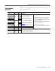
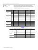
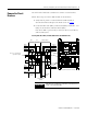
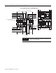
Table Of Contents
- Front Cover
- About This Publication
- Important User Information
- Catalog Number Explanation
- Field Replaceable Components
- Remove/Replace the Front Cover
- Remove the Circuit Breakers
- Replace the Circuit Breakers
- Remove the Auxiliary Contact
- Replace the Auxiliary Contact
- Remove and Replace the Fuse Block
- Replace the (FB1) Fuses
- Remove the Cooling Fan
- Replace the Cooling Fan
- Block Diagrams
- Additional Resources
- Back Cover
Publication 2094-IN009C-EN-P — April 2008
Removing and Replacing the Line Interface Module Internal Components 9
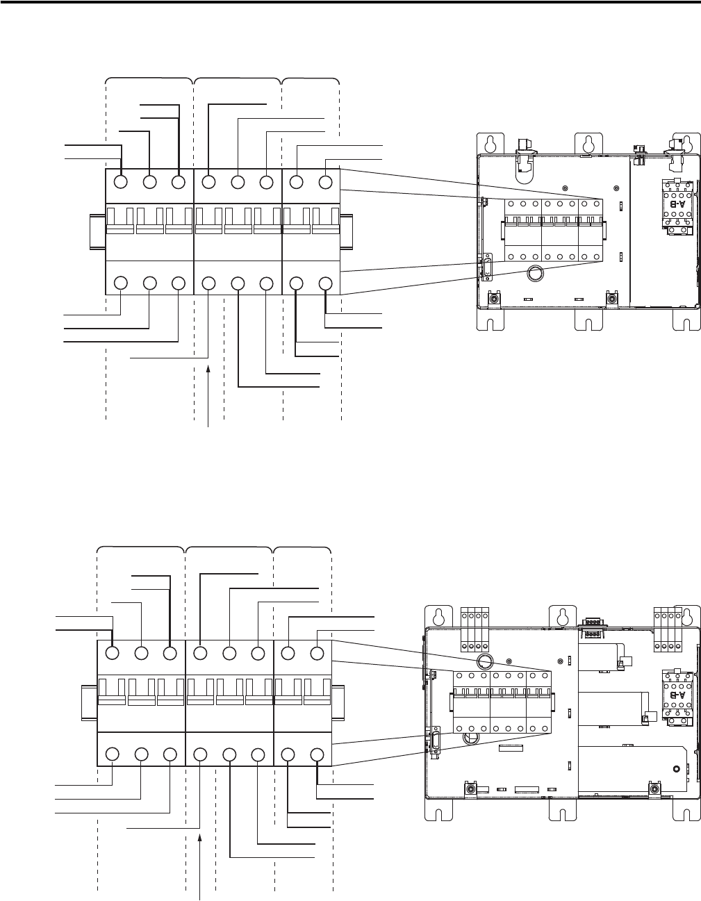
Locating CB1, CB2_AUX, CB2, and CB3 (2094-AL09)
Locating CB1, CB2_AUX, CB2, and CB3 (2094-BL02)
1
3513
1
3
2
4
624
24
WIRE_1
L1
WIRE_8
WIRE_9
WIRE_6
WIRE_7
AUXSTAT_1
WIRE_3
WIRE_4
WIRE_5
AUXSTAT_2
WIRE_14
WIRE_16
WIRE_2
L3
L2
WIRE_13
WIRE_15
230VAC_L1
230VAC_L2
5
6
CB3
CB1
CB2
Control VAC
(CB2)
Brake and I/O
(24V ac)
Auxiliary Contact
(CB2_AUX)
Line Interface Module
(2094-AL09 module is shown)
Main VAC
(230/460V ac)
1
3513
1
3
2
4
624
24
WIRE_10
WIRE_11
WIRE_8
WIRE_9
WIRE_5
WIRE_6
WIRE_7
AUXSTAT_2
WIRE_1
L1
WIRE_2
L3
L2
AUXSTAT_1
WIRE_16
WIRE_18
WIRE_15
WIRE_17
230VAC_L1
230VAC_L2
5
6
Line Interface Module
(2094-BL02 module is shown)
CB3
CB1
CB2
Control VAC
(CB2)
Brake and I/O
(24V ac)
Auxiliary Contact
(CB2_AUX)
Main VAC
(230/460V ac)