
Instruction Manual
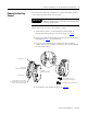

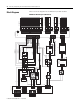
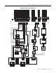
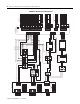
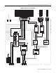
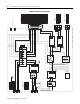
Table Of Contents
- Front Cover
- About This Publication
- Important User Information
- Catalog Number Explanation
- Field Replaceable Components
- Remove/Replace the Front Cover
- Remove the Circuit Breakers
- Replace the Circuit Breakers
- Remove the Auxiliary Contact
- Replace the Auxiliary Contact
- Remove and Replace the Fuse Block
- Replace the (FB1) Fuses
- Remove the Cooling Fan
- Replace the Cooling Fan
- Block Diagrams
- Additional Resources
- Back Cover
Publication 2094-IN009C-EN-P — April 2008
Removing and Replacing the Line Interface Module Internal Components 11
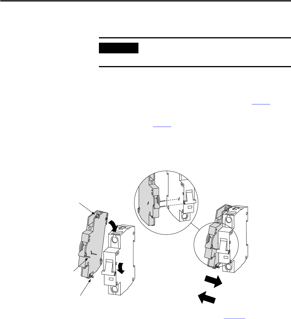
Remove the Auxiliary
Contact
You will need a flat-blade screwdriver to remove the CB2A auxiliary
contact from the CB2 control circuit breaker.
Follow these steps to remove the auxiliary contact.
1. Verify that all power is removed from the LIM module as
described in Remove/Replace the Front Cover on page 5
.
2. Remove the CB2 assembly (refer to Remove the Circuit Breakers
beginning on page 7
for instructions).
3. Locate the clip fastener on the bottom side of the auxiliary
contact and use a screwdriver to gently pry the clip downward
to release the contact.
4. Go to Replace the Auxiliary Contact on page 12
.
IMPORTANT
This procedure applies to only the auxiliary contact in 2094-ALxxS,
2094-BLxxS, and 2094-XL75S-Cx LIM modules. Other LIM modules do
not have an auxiliary contact.
Hang top clip in slot and
snap together when replacing.
Top clip pivots in slot.
Release clip and pivot apart to remove.
1492-ASPH3
Auxiliary Contact (CB2A)
Pins align in holes.
Bottom clip latches when contact
and circuit breaker are pressed together
(releases when gently pried apart).
1492-SP
Circuit Breaker (CB2)